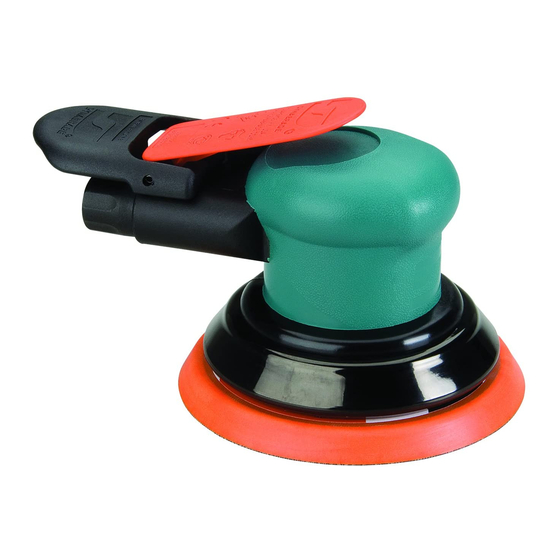
Dynabrade Dynorbital-Spirit 21060 Manual - Página 8
Navegue en línea o descargue pdf Manual para Sander Dynabrade Dynorbital-Spirit 21060. Dynabrade Dynorbital-Spirit 21060 13 páginas. 12,000 rpm air powered random orbital sander
También para Dynabrade Dynorbital-Spirit 21060: Manual de instrucciones de funcionamiento y mantenimiento (8 páginas), Manual de funcionamiento y mantenimiento (13 páginas)

Buy parts on line at https://Dynashop.co.uk/ for all things Dynabrade
Motor Assembly/Disassembly Instructions - Dynorbital -Spirit
Drawing 3
To Assemble (Continued):
11. Install the
58368
Bearing into the
12. Use the small end of the
57091
Drawing 5. Press the bearing/plate down until it touches the cylinder. This should create a snug fit between the bearing plates and cylinder.
13. Install the
01024
O-Ring into the cylinder and apply a small amount of the Dynabrade Air Lube onto the o-ring.
14. Coat the
50659
O-Ring with the Dynabrade Air Lube and install it into the
the 3/16" orbit sanders.
15. Place a mark on the edge of the motor opening to identify the location of the line-up notch on the inside of the housing.
16. Install the motor assembly into the housing. Be certain that the line-up pin enters the notch in the housing.
17. Use the
57092
Collar to carefully hold the tool in a vise so that the counter balance is pointing up.
18. Use the
56058
Lock Ring Tool to tighten the
19. Use the 26mm open-end wrench to install a weight-mated sanding pad.
Valve and Speed Regulator Assemblies:
1. Secure housing in vice using
57092
2. Remove inlet bushing,
01468
3. Remove
95697
Snap Ring. Press the speed regulator and valve stem out of the housing. Remove the
4. Place new
01025
O-Rings (2) on the speed regulator and a new
95967
Snap Ring. Apply a small amount of pneumatic tool oil to valve o-rings.
5. Place new
01464
Seal in housing. Using tweezers or needle nose pliers, place the tip valve into housing so that the tip valve goes under the valve
stem. Place new
01468
Spring into housing so small end is towards tip valve.
6. Apply a small amount of #567 Loctite
7. Install Lever on housing with
98927
Note: Motor should operate at between 11,000 and 12,000 RPM at 6.2 bar (90 PSIG). RPM should be checked with a tachometer. Before operating,
we recommend that 2-3 drops of Dynabrade Air Lube P/N
machine for approximately 30 seconds before application to workpiece to determine if machine is working properly and safely and to allow lubricating
oils to properly dispense through machine.
Loctite
®
is a registered trademark of the Loctite Corp.
Disc Pad Change:
1. Insert
50679
Wrench on flats of
2. With wrench still in place, hand tighten new pad on tool.
3. No need to remove shroud or overskirt.
Required Weight of Pads:
3" Models –– Use pad weighing 75g.
3-1/2" Models –– Use pad weighing 80g.
5" Models –– Use pad weighing 100g.
6" Models –– Use pad weighing 130g.
Buy parts on line at https://Dynashop.co.uk/ for all things Dynabrade
57091
Bearing Press Tool
Front Bearing
Motor Shaft Balancer
Balancer Shaft Assembly
59077
Rear Bearing Plate.
Bearing Press Tool and the arbor press to install the rear bearing/plate onto the motor shaft balancer as is shown in
59058
Lock Ring by turning it clockwise. (Torque to 23 N•m/200 in.- lbs.)
Collar or padded jaws.
Spring,
58365
Tip Valve and
01464
98459
®
(or equivalent) around the threads of the first inlet bushing and tighten into housing to 23 N•m/200 in. - lbs.
Pin centered on housing.
95842
(or equivalent) be placed directly into the air inlet with throttle lever depressed. Operate the
57069
Balancer Shaft and twist off sanding pad by hand.
Drawing 4
59058
Lock Ring. Slip these over the counter weight of the 3/32' and
Seal from housing. Remove
98927
O-Ring on the valve stem. Then place in housing with valve stem. Install new
8
57091
Bearing Press Tool
Front Bearing
Motor Shaft Balancer
Balancer Shaft Assembly
Pin from housing and lever.
01025
O-Rings (2) and
98459
O-Ring.
Drawing 5
57091
Bearing Press Tool
59077
Rear Bearing Plate
(with
58368
Line-Up Pin
59051
Cylinder Assembly
(w/Rotor and Vanes)
59076
Front Bearing Plate
(with
58368
Motor Shaft Balancer
Balancer Shaft Assembly
™
Bearing)
Bearing)
