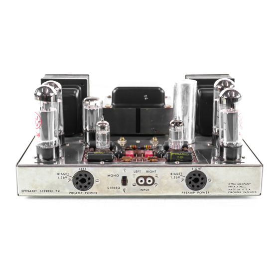
DYNACO Stereo 70 Instrucciones de montaje - Página 5
Navegue en línea o descargue pdf Instrucciones de montaje para Amplificador DYNACO Stereo 70. DYNACO Stereo 70 16 páginas. Series ii tube amplifier
También para DYNACO Stereo 70: Manual de restauración (20 páginas), Manual de restauración (5 páginas), Manual del usuario (12 páginas)

9 (L1 Mount the SPST on-off switch (two lugs) on
the chassis rear. The con nee tin g lugs
should be located as shown in the pictorial
diagram. No lockwashers or nuts are
necessary.
WIRING PROCEDURE
EACH LENGTH OF HOOKUP WIRE SPECIFIED
SHOULD HAVE APPROXIMATELY 1/4" OF
INSULATION STRIPPED FROM
EACH END
UNLESS OTHERWISE SP ECIFIED.
13 (---) Mount both A-470 output transformers with
#8 hardware. Note that the shorter leads
come through the holes in the rear.
12
(-1
Us ing 4/40 hardware, mount the seven lug
terminal strip on the left side opposite the
choke, following the pos ition shown in the
pictorial diagram.
11 ( )
Mount the choke, C-354, on the right side
below the c has sis.
Put the #8 screws
through the chassis from the top and fasten
underneath with lockwashers and nuts. The
leads should face the front of the chassis.
3
I
(V[
Connect the red-black transformer lead to
the lower
(+)
lug of the selenium rectifier
(S) .
2 (
'1
Twist the pair of white leads and dress
them from the power transformer to socket
VI.
Connect one lead to pin #2 of VI (S).
Connect the other white lead to pin
#8
of VI.
3 ('-) Twist the red pair of leads and dress them
to socket
VI.
Connect one red lead to pin
#4 of VI (S).
Connect the other red lead to
pin #6 of VI (S).
4 (?1 Twist the pair of green leads together and
dress to socket V2.
Connect one green
lead to pin 1/2 of V2.
Connect the other
green lead to pin #7 of V2.
5
('/1'
Twist the brown pair and dress them to
socket V7.
Connect one brown lead to pin
#2 of V7.
Connect the other brown lead to
pin #7 of V7.
6 (
'1'
Dress the brown -yellow and green -yellow
leads a
I' 0
un d to the s even lug terminal
strip. Connect the brown -yellow to lug #7
and the green-yellow to lug #5.
7
(1.-1
Connect the red -yellow lead to the solder
lug near the filter capacitor.
8
(-1
Feed the red lead from the left
0
u t put
transformer through both cable clamps and
the red lead from the right output trans-
former through the right clamp.
Connect
both red leads to filter capacitor lug
#1.
(The lead from the right output transformer
can be trimmed to the required length).
9 ('/) Feed the two choke leads through the right
cable clamp, con n e c t one lead to filter
capacitor lug #2 and the other lead to lug
4{
1.
(These leads can be trimmed as re-
qUired).
Tighten the two nuts holding the
cable clamps.
10 (v') Dress the power transformer black leads
around the end bell and connect one lead to
lug A of the fuse post (S).
Connect other
black lead to lug #l of on -off switch (S).
11
('1
Connect the short black lead from the right
output transformer to lug #4 of the 4 screw
terminal strip.
Connect the brown lead to
lug #3 (S).
Connect the orange lead to lug
#2 (S).
Connect the yellow lead to lug #
1.
Mount the quadruple section filter capacitor
in the special cutout.
Fasten by twisting
each mounting tab one -quarter turn. Note
that the four connecting lugs are identified
by markings at the base of the lugs.
Be
sure to orient the capacitor properly, with
the lugs positioned as in the pictorial.
Mount two solder lugs with a #4 screw and
nut next to the quad filter capacitor. This
is the main grounding point of the entire
amplifier and should be tightened securely
with the two lugs pointing as shown in the
pictorial.
10 (...y-Mount the power transformer, PA-060, in
the large center cutout. The wires should
face the front of the chassis.
Fasten the
two mounting screws at the rear with
#8
lockwashers and nuts. Place a cable clamp
over each of the two front mounting screws
and fasten loosely with
118
lockwashers and
nuts.
The green, red, and white pairs of
wires should be threaded through the left
cable c
I
amp as should the green -yellow
and brown-yellow ones.
Pass the brown
pair through the right clamp.
14
U)
MOST TRANSFORMER LEADS ARE PRE-CUT
TO THE PROPER LENGT HS AND DO NOT
REQUIRE CUTTING.
HOWEVER, THEY CAN BE
SHORTENED WHERE DESIRED.
IT IS ESSEN-
TIAL THAT THEY NOT BE CUT TOO SHORT
FOR CONNECTIONS WHEN THE
LEADS ARE
POSITIONED IN A C COR DAN C E WITH THE
PICTORIAL DIAGRAM.
IN THE EVENT THAT
THE TRANSFORMERS ARE RETURNED TO THE
FACTORY FOR REPLACEMENT
OR INSPEC-
TION, THE
LE ADS ,MUST BE OF U SAB LE
LENGT H OR THE WARRANTY WILL BE
VOIDED.
