HiB Hush Chrome Instrucciones de montaje - Página 2
Navegue en línea o descargue pdf Instrucciones de montaje para Ventilador HiB Hush Chrome. HiB Hush Chrome 3 páginas. Wall mounted fans, timer/timer & humidity sensor
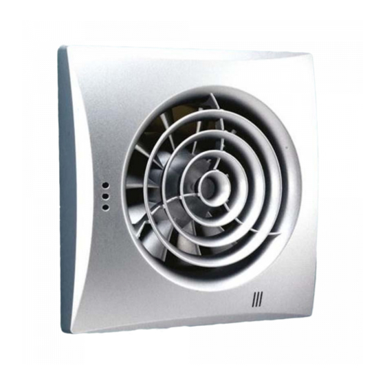
Technical Information -
Hush
Power input: 220-240 V, 50 Hz
Maximum ventilation volume: 97 m
3
/hr (±5%)
Power consumption: 7.5W
Dimensions: W158 x H158 x D107mm
Breeze
Power input: 220-240 V, 50 Hz
Maximum ventilation volume: 88 m
3
/hr (±5%)
Power consumption: 14W
Dimensions: W152 x H152 x D126mm
Fitting
1) Choose a suitable position for your fan
according to Figure 1 on the back page. Use
a cable finder to check if there are any buried
cables or pipes in the wall or ceiling. Draw
around the outside of the fan with a pencil to
determine it's exact position.
2) Make a suitable sized hole in the wall/
ceiling with the appriopiate tools.
N.B. If wall mounted ensure the hole is
angled slightly downward to stop any
moisture running back into the motor.
If mounted in the ceiling ensure the hole is
between the joists.
3) Fit flexible ducting into the hole, flush
with both sides of the wall. Ensure the
duct slopes slightly downwards towards
the outside. Make good any plasterwork
around the duct.
4) Position the fan back into place, and mark
the four fixing points. Drill the required
holes in the marked positions. If drilling
through tile, use a ceramic drill bit. Insert
wall plugs into the drilled holes.
5) Follow a similar procedure for the outside
wall grille.
6) If ceiling mounted the ducting should be
routed to the nearest soffit.
2
Electrical Connection
Hush
Please ensure that the fan unit is positioned in
accordance with the diagram below i.e. With
the electrical access point (5) top left.
4
5
1
2
3
1
Casing
2
Fan propeller
3
Function module
4
Protective cover of terminal block
5
Electrical access point
Breeze
3
4
2
1
1
Holes for fan mounting (x4)
2
Terminal block
3
Electrical access points
4
Wire fixing rack
Fascia removal
Hush
- Depress plastic nodule on the side of the
fascia and gently prise away from the casing.
Breeze
- In order to remove the fascia for
maintenance, please remove the small retaining
screw and gently prise the fascia away from the
casing.
1) Ensure the domestic electrical mains supply
to which the fan is being connected is turned
off. This product is designed to be connected
to an on/off switch outside the bathroom, or
to a ceiling mounted pull cord switch.
2) Hush Only: Remove the front panel and
protective cover (4). Pass the power wire
through the hole in the rubber plug (beneath
protective cover) at the fan casing flange.
3) Breeze Only: Remove the protective grille.
Cut out blanking plug of electrical access
point (3) and lead the power supply cords
through the hole.
4) Make the electric connections according
to the relevant wiring diagram below. See
diagram of ceiling rose to ensure correct
feeds are used.
Please note that the
fan may operate immediately when
connected, this is normal and due to a
residual charge left during testing.
Hush
S
220 - 240 V
Breeze
S
220 - 240 V
Ceiling Rose
LAMP/FAN
5) Fix the fan to the wall using 4 screws.
6) Replace the cover and protective grille.
Ceiling mounted...
For ceiling mounting follow procedure for wall
mounting making sure ducting isn't mounted
vertically to the outside. This is to ensure
moisture doesn't come back into the motor.
Do not
mount vertically
Operating Instructions
1) For Art Nos. 33100/31700/31500/
32800/31300/31100
Fan with timer option switches on as control
voltage is supplied to LT terminal. After
voltage is off, the fan continues operating
within the set time period T, adjustable
between 2 and 30 min. The time is regulated
by turning the potentiometer T clockwise to
increase and anticlockwise to decrease the
run time.
2) For Art Nos. 33200/31800/31600/3290
0/31400/31200
Fan with timer and humidity sensor will
operate when a control voltage is applied
to the LT terminal OR when the humidity
exceeds that set on the potentiometer.
If this is set at its lowest (60%) the fan
will run most of the time. When set at the
highest setting (90%) the fan will only
operate at higher level humidity. Once
humidity has been reduced the fan will
run until the required setting on the timer
is reached. Time T and humidity H values
are regulated by turning the appropriate
potentiometers T and H clockwise to
incr ease and anticlockwise to decrease
the running-out time and humidity level
respectively. To set the maximum humidity
level set the potentiometer in H max (90%)
position.
N.B. Always use the plastic screwdriver provided
to adjust the settings to avoid damaging the
control unit.
1) Maintenance
Fan maintenance is to be performed only after
the fan is disconnected from the mains power
supply. Maintenance means periodic clearing
of the surfaces from dust and dirt.
hib.co.uk
3