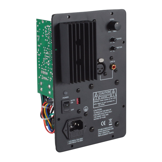
DaytonAudio MCA3545 Manual del usuario - Página 2
Navegue en línea o descargue pdf Manual del usuario para Amplificador DaytonAudio MCA3545. DaytonAudio MCA3545 4 páginas. 80 watt bi-amplifier

Thank you for purchasing the MCA3545 Bi-Amplifier. It was designed and built to provide years of high quality sound reproduction
when used in active 2-way loudspeakers for music playback, computer sound systems, and home theater applications. The ampli-
fier includes features like user selectable high pass and low pass filters, independent high and low frequency level controls, rugged
independent LM3886TF output devices, and comprehensive internal protection against shorted speaker loads, thermal faults, and
overload conditions.
Features
:
• User selectable high and low frequency crossover points
• Independent LM3886TF output devices
• Master level control
• Independent high and low level controls
• Switchable 3dB low frequency boost
Front Panel Controls/Connections
1. Power Status LED
The power LED illuminates when the power switch is in the ON
position. After 20 minutes of no signal the unit will go into stand-
by mode and the LED will dim.
2. Power Switch (Off/Auto On)
The amplifier is manually turned ON or OFF via this switch. When
in stand-by mode, (no signal present) the current draw and heat
generated is very low, therefore it can be left in the ON position
indefinitely. The unit will go into stand-by mode if no signal is
present for 20 minutes.
3. Voltage Selector Switch
This switch allows the user to select 115V or 230V operation. The
unit is set at the factory for 115V operation.When operating at 230V
be sure to change the fuse to a slow blow 1A, 250V type fuse.
4. IEC Power Jack
This unit features a grounded IEC type power jack. This allows
the user to change the power cord depending on the country and
voltage used. The IEC jack also houses the fuse holder which
uses 5mm x 20mm, slow blow 250V type fuse. The unit is set at
the factory for 115V operation and is supplied with a USA type
power cord and a 2A slow blow 250V fuse.
5. Level Control
This is the "master" level control that adjusts the overall output level
(both high and low level simultaneously) of the amplifier.
6. Woofer Control
Independently adjusts low frequency output level, to the woofer
only. Adjustment range is 0~+5dB.
7. Tweeter Control
Independently adjusts high frequency output level, to the tweeter
only. Adjustment range is 0 ~ +3dB .
NOTE: Independent woofer and tweeter adjustments allow precise
speaker component balancing, compensating for different levels
in program material and varying room acoustics.
8. RCA Input
RCA connection accepts standard 1Vp-p line level signal. This
is the unbalanced line level input for connection to standard
consumer grade equipment and audio equipment commonly used
in home applications
9. XLR Input
This is the balanced line level input for connection to mixing
consoles and other professional type audio equipment commonly
used in studio applications
All manuals and user guides at all-guides.com
(2)
• 24dB / octave high pass and low pass filters
• Balanced and unbalanced line level input
• Thermal, overload and fuse protection circuitry
• Auto On/Off stand-by circuit
• Operates on 115V of 230V
Output Connections
Speaker Outputs
There are two sets of speaker outputs located on the rear (PC
board side) of the amplifier module. Each color coded red (+)
and black (-). The black or negative wire features a .110" push
on connector and the red or positive wire uses a .187" push on
connector .Output connections listed below assume you are facing
the rear of the amplifier module (PC board side), with the power
transformer located to the left. Loads on each output lead must
have a nominal impedance of 8 ohm or higher.
Tweeter
This output connection is located on the far right side of the main
amplifier PC board. Note the red and black leads are connected
to corresponding tabs on the PC board labeled T+ and T -.
Woofer
This output connection is located towards the middle left side of
the main amplifier PC board, approximately 2-1/2" from the left
edge of the board. Note the red and black leads are connected to
corresponding tabs on the PC board labeled W+ and W -.
