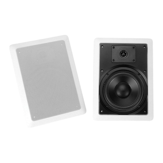
DaytonAudio CONTRACTOR Series Manual del usuario - Página 3
Navegue en línea o descargue pdf Manual del usuario para Altavoces DaytonAudio CONTRACTOR Series. DaytonAudio CONTRACTOR Series 4 páginas. In-wall speaker
También para DaytonAudio CONTRACTOR Series: Manual del usuario (2 páginas), Manual del usuario (2 páginas)

5.
Speaker Cable
Don't compromise sound quality by using thin, inexpensive
speaker wire, we recommend using a high quality oxygen
free copper speaker cable. For runs less than 50 feet,
we recommend 16 gauge cable, and for longer runs we
recommend 14 gauge or larger cable. For installations with
in-room stereo volume controls we recommend using a four
conductor speaker wire from receiver to volume controls. Most
municipalities require the use of CL2 rated speaker cable
for installation in walls and ceilings. Leave enough speaker
cable so you can stand comfortably on the floor or ladder while
connecting the speaker cable to the speakers.
6.
Speaker Connection
Remove about 8" of the cable jacket to expose the inner
conductors. Strip 1/4" of insulation from each conductor and
connect to the speaker terminals. When connecting the wires
to the speakers, be sure to observe proper polarity. Most CL2
rated speaker cable will have red and black conductors so you will
connect the red wire to the red speaker terminal and the black
wire to the black speaker terminal.
For high impedance (70 V) applications attach the positive lead
from the receiver to the wattage lead on 70 V transformer to be
used (i.e. 2.5W) and the negative lead from the receiver to the
to the common ground lead (C) on 70 V transformer. For low
impedance (8 ohm) applications connect the positive lead from
the receiver to the RED positive terminal on the speaker and the
negative lead from the receiver to the BLACK negative terminal
on the speaker. Note: To avoid damage to the speaker, be sure to
switch off the amplifier power when changing the input.
7.
Final Installation
To install the speakers into the ceiling, remove the grills,
this will give you access to the mounting screws. Turn the
mounting clamps so they are positioned as in the illustration,
this will allow the speakers to clear the hole for installation.
Insert the speaker into the hole, and tighten the mounting
screws. As you turn each screw, the mounting clamps will
rotate outward to engage ceiling material.
CAUTION: Do Not Over-Tighten the Clamps. Too much torque may snap off the lug and the
speaker will not seat securely. A snug fit is all that is necessary to assure proper performance.
8.
Painting Speakers
If you choose to paint the speaker grill and/or frame we have provided a "Paint Masking Tem-
plate" to cover the woofer/tweeter assembly and help prevent possible damage. Do not try to
paint the frame and grill assembly together. The grill should always be painted separately.
Do not apply heavy coats of paint that might block the perforations in the grill.
9.
Troubleshooting
Should your speakers not work properly, check the following:
No sound from speakers:
G
Most stereo receivers have an A/B speaker selector switch. Make certain that
this switch is in the proper position.
G
Mute feature is activated.
One speaker is playing while the other is not:
G
Check the balance control on the receiver. Make sure it is centered.
G
Loose connection at either the receiver or the speaker. Double check connections.
G
Bad speaker cable. Replace suspect speaker cable.
