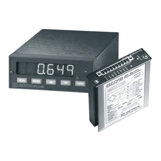
DayTronic 5D78 Manual de instrucciones - Página 7
Navegue en línea o descargue pdf Manual de instrucciones para Instrumentos de medida DayTronic 5D78. DayTronic 5D78 20 páginas. Panel meter, ac strain gage conditioner module

S
PECIFICATIONS
M
3000PLUS
ODEL
Case: Extruded metal chassis, mountable to user's panel (see
Section 1.C); secure rear connections via screw terminals
Dimensions: See Fig. 1, below
Power Requirements: 24 VDC ± 10%; 300 mA nom.; 350 mA
max.; 8.4 W; optional AC adaptor (Model 3KPS1) available
Operating Temperature Range: 0° F to 130° F (-18° C to
55° C)
Operating Relative Humidity: 10% to 95%, noncondensing
Instrument Weight: 1 lb., 10 oz. with 5D module installed
A/D Conversion: 16-bit
Sample Rate: 10 kHz; delay of 20-25 msec for limit evaluation
of DAC output
Data Display: 6-digit red LED; count by 1, 2, or 5 resolution to
maximum count of 199990 (see Section 1.D); selectable dig-
ital filtering
Displayable Data Channels: (1) ±5 VDC Scaled Output; (2)
Auxiliary DAC Output; (3) Scaled Voltage Output; selectable
via front panel or software
Programmable Processing of Auxiliary DAC Output
(Channel 2):
Limit Logic: Three limit zones (LOW/OK/HIGH) with front-
panel annunciation and corresponding contact relay out-
puts (see below); latching or nonlatching limits;
user-adjustable hysteresis windows; selectable relay
polarity
Positive and Negative Peak Capture: Controlled by logic
input (see below); selectable "peak defeat" and "backout"
thresholds; user-adjustable leak rate
Tare Offset: User-adjustable offset applied and released via
logic input (see below)
Hold Command: Applied and released via logic input (see
below) or software command
Analog Output (Channel 3): Selectable ± 0 to 5 VDC, ± 0 to
10 VDC, or 4-20 mA, single-ended; 14-bit resolution; 47-Hz
filter; update rate of 20 msec
TTL Logic Inputs (UNLATCH, TARE, PEAK, HOLD) and Out-
put (HAVE PEAK): Nominal 0 - 5 V, where 5 V = Logic 1
Fig. 1
3000PLUS Dimensions
4.41 "
3000PLUS
WITH
("true"); ±25 V without damage; noise immunity 1 V; internal
pull-down nom. 4.7 kΩ; all inputs assume Logic 0 state in the
absence of connection
Relay Logic Outputs (LIMIT HI, LIMIT OK, LIMIT LO): Two for
each limit; selectable polarity; 8 A, 250 VAC at full resistive
load; switch lifetime at 1 A exceeds 100,000 operations
Communications: Three-wire RS232 at fixed 19,200 Baud, 8
Data Bits, 1 Stop Bit, No Parity; for setup and data transfer
Front-Panel Instrument Indication: Limit status, displayed
channel, setup stage, and overrange (flashing display)
M
ODEL
Input Overvoltage Protection: Up to 240 VAC rms on all Sig-
nal and Excitation lines
ESD Protection: Up to 4 kV on all connections
Isolation: 1500 VAC between input and output terminals; 1500
VAC between I/O terminals and power supply / communica-
tions terminals
Transducer Types: Conventional 4-arm strain gage bridges,
typically transformer-coupled, 120 Ω to 10 kΩ; zero range is
20% of the stated full scale. A screw terminal is provided for
user-supplied shunt calibration resistor (see Fig. 8).
Input Ranges (Full-Scale): See Table 1, below; selectable
when the 3000PLUS meter is configured (NOTE: the highest
range selection accommodates actual inputs as high as 4.8
mV/V*)
Excitation Frequency: 3.27, 5.00, or 10.00 kHz; selectable
when the 3000PLUS meter is configured
Excitation Voltage: Nominal 3 VAC rms
Accuracy: Dependent on range and excitation; see Table 1
Amplifier:
Normal-Mode Range: 15 V rms operating; 240 V rms with-
out damage
Input Impedance (Differential): Greater than 350 kΩ
Offset: Initial: ±0.05% of full scale; vs. temperature: ±25
ppm/°C; vs. time: ±10 ppm/month
* See Table 2 in Appendix B for the "practical" ranges that apply
to the 5D78 RANGE (RNG) setting.
1.70 "
5D78 I
NSTRUCTION
1. I
NTRODUCTION
5D78
7.17 "
M
. SB.3
ANUAL V
(cont'd)
0.22 "
3KP78 - 1.3
