GAI-Tronics PHP400 Manual de instalación y uso - Página 6
Navegue en línea o descargue pdf Manual de instalación y uso para Teléfono de emergencia GAI-Tronics PHP400. GAI-Tronics PHP400 20 páginas. Analogue version (1090/1099 series) with ampetronic hls-dm2 induction loop amplifier 230v ac power supply
También para GAI-Tronics PHP400: Manual de instalación y uso (20 páginas), Manual de diseño, instalación y uso (20 páginas)
Installation and dimensions
5.
General
5.1.
All possible measures must be taken to ensure water, fluid or dust does not
contaminate the internal components of the unit whilst unpacking, preparing and
installing it in inclement weather conditions or by negligence.
Do not drill any additional holes in the casing. Make sure any unused cable
entry or mounting holes are properly sealed against water or dust ingress.
Failure to do so may result in an unsafe condition and will invalidate your
warranty.
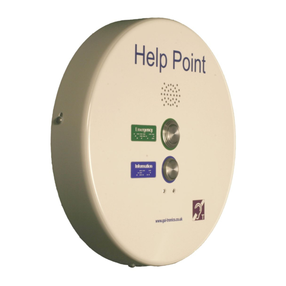
Units dimensions and weight
5.2.
Overall diameter
Depth (rear surface to front face)
Pushbutton height from front face
Unit weight
Mounting centres
Cable entries
Site requirements
5.3.
Ensure that the following are available before installation:
1. Power supply: 230Vac @ 0.5A (cables must be capable of carrying 5A min).
2. Analogue telephone line
3. This is normally a two-person installation, due to the size/weight of the unit and due
to the need to connect cables between the 2 sections.
Opening the Unit
5.4.
To open the case, undo the 4 security screws around the edge of the unit. These
screws are normally Torx type with a centre security pin.
The front section is fitted over the rear section and can be gently lifted clear.
Take care when separating the 2 sections – there are up to 4 cable sets between the 2
halves:
IMPORTANT
405mm
88mm
10mm
6.5kg
4 x 7mm holes on 145 x 270mm centres,
see drawing 112-11-0081-001 appended to
this manual.
5 off 20mm gland entry points are provided,
with blanking plugs to blank off any that are
not used:
2 x rear
2 x lower
1 x upper
Positions are detailed on drawing
112-11-0081-001 appended to this manual.
PHP400 Analogue Help Point.
6