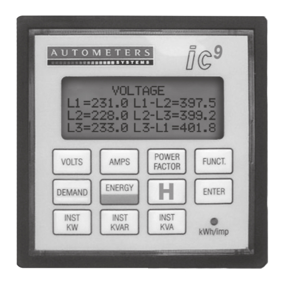
Autometers Systems IC7-C Manual de instalación y funcionamiento - Página 7
Navegue en línea o descargue pdf Manual de instalación y funcionamiento para Instrumentos de medida Autometers Systems IC7-C. Autometers Systems IC7-C 9 páginas.

Wiring Information
Power Supply
The standard IC7-C and IC9-C
requires a 230 volt, 50Hz supply.
This is provided from the L3
phase and Neutral internally.
Wiring
Electrical and communication
connections are made to
terminals 1-6 at the lower half
of the meter. Communication
Modbus 485 connections are
made via the two sockets at the
top of the meter on the side.
Please see diagram 3.
Programming the
Meter
To program the meter the dill
switch, number "8" on the lower
dill switch block must be in the
"on" position.
Programming the Modbus
Meter Register
Each meter that is connected to
a Local Area Network (LAN) must
have a unique modbus register
so that it can be identified by the
computer processor. Allocating
a meter modbus register is
accomplished using the upper
block of dill switches. The dill
switches in this block each
represent a number, in geometric
progression starting with dill
switch number "8". Thus switch
number "8" represents register
number "1", switch number "7"
represents register number "2",
switch number "6" represents
register number "4", switch
number "5" represents register
number "8" and so on.
To allocate a meter register
number the required dill switches
must be switched into the "on"
(up) position.
TOP SWITCH
ON
DIP
MODBUS
ADDRESS
1
1
2
2
3
3
4
4
5
5
6
6
7
7
8
8
LOWER SWITCH
ON
DIP
MODBUS
PARAMETERS
1
1
2
2
3
3
4
4
5
5
6
6
7
7
8
8
Thus: To allocate meter register
number "1", only dill switch
number "8" on the upper block
of dill switches needs to be in the
"on" position.
To allocate meter register number
"14" dill switches numbers "5",
"6" and "7" must be in the "on"
position.
To allocate meter register number
"39" dill switches numbers "3",
"6", "7" and "8" must be in the
"on" position. Etc.
Programming the
Meter Functions.
The operating functions of the
meter, such as baud rate, data
format etc are programmed using
the lower block of dill switches,
as follows:
Baud Rate
Programming the Baud rate
utilises dill switches numbered
"1" and "2" on the lower dill
switch block, as follows:
Baud Rate Dill Switch Dill Switch
1
9600
Off
19200
On
38400
Off
1200
On
Wire Mode
Programming wire mode utilises
switch number "3", as follows:
Two wire mode: switch Off
Four wire mode: switch On
7
Modbus Type
Programming the modbus type
utilises switch number "4", as
follows:
RTU: switch Off
ASCII: switch On
Parity Type
Programming the parity type
utilises switch number "5", as
follows:
Even: switch Off
Odd: switch On
Data Format
Programming data type utilises
switch number "6", as follows:
ASCII string:
Floating point: On
Floating Point Format
Programming the floating point
format utilises switch number
"7", as follows:
High word first: switch Off
Low word first: switch On
LED Mode
Programming the LED mode and
CT ratio utilises switch number
"8", as follows:
Calibration 1000 impulses per
2
Kwh: switch On
Off
Kwh impulse with output relay:
Off
switch Off
On
On
Off
