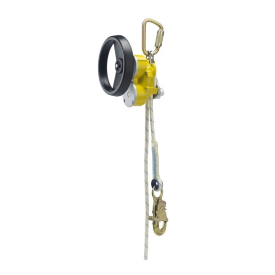
DBI SALA ROLLGLISS R550 Manual de instrucciones - Página 2
Navegue en línea o descargue pdf Manual de instrucciones para Sensores de seguridad DBI SALA ROLLGLISS R550. DBI SALA ROLLGLISS R550 16 páginas. Rescue & escape device

1.0 APPlIcATION
1.1
PuRPosE: The R550 Rescue & Escape Device is intended to lower one or two people simultaneously from
an elevated height to a lower level in a rescue situation. Multiple people may descend one after another
using the device. The descent speed is automatically limited during descent. Models incorporating a hand
wheel allow for raising persons a short distance to facilitate rescue.
WARNING:
The R550 Rescue & Escape Device is for Rescue purposes only. It must not be used as a fall arrest device.
1.2
LIMITATIoNs: The following application limitations must be recognized and considered before using this product:
A.
CAPACITY: Required capacities and descent distances for the Rollgliss R550 are as follows:
Total Weight
users
(including tools, clothing, etc.)
2 Persons
130 lbs (59 kg) - 620 lbs (282 kg)
1 Person
130 lbs (59 kg) - 310 lbs (141 kg)
1 Person
130 lbs (59 kg) - 220 lbs (100 kg)
1 Person
130 lbs (59 kg) - 165 lbs (75 kg)
B.
MAXIMuM DEsCENT DIsTANCE AND MAXIMuM NuMBER oF DEsCENTs: See Section 10.0
Descent Log for instructions to calculate the allowed Maximum Cumulative Descent Distance.
C.
DEsCENT sPEED: The speed at which the user(s) will be lowered when using the Rollgliss R550 Rescue
& Escape Device increases with the combined weight of the user(s). The approximate descent speed for
one person is 2-3 ft/s (0.6 - 0.9 m/s). The approximate descent speed for two persons is 2 ft/s - 4 ft/s
(0.6 m/s - 1.2 m/s).
D. HAZARDous AREAs: Use of this equipment in hazardous areas may require additional precautions to
reduce the possibility of injury to the user or damage to the equipment. Hazards may include, but are
not limited to: high heat, caustic chemicals, corrosive environments, high voltage power lines, explosive
or toxic gases, moving machinery, and sharp edges.
E. TRAINING: This equipment is intended to be installed and used by persons trained in its correct
application and use.
1.3
APPLICABLE sTANDARDs: Refer to ANSI/ASSE Z359.1, Z359.4, CSA Z259.2.3 and other applicable local,
state, and federal (OSHA) standards for requirements governing the use of this equipment.
2.0 sysTeM ReqUIReMeNTs
2.1
CoMPATIBILITY oF CoMPoNENTs: DBI-SALA equipment is designed for use with DBI-SALA approved
components and subsystems only. Substitutions or replacements made with non-approved components or subsystems
may jeopardize compatibility of equipment and may effect the safety and reliability of the complete system.
2.2
CoMPATIBILITY oF CoNNECToRs: Connectors (hooks, carabiners, D-rings) used to suspend the
R550 Rescue & Escape Devices must be capable of supporting at least 3,000 lbs (1,361 kg). Connectors
must be compatible in size, shape, and strength. Non compatible connectors may unintentionally disengage
(roll-out). Roll-out occurs when interference between the connector and anchorage connector causes the
hook or carabiner gate to unintentionally open and release. Self locking snap hooks and carabiners must be
used with this system to reduce the possibility of roll-out. Do not use connectors that will not completely
close over the attachment element.
2.3
ANCHoRAGE sTRENGTH - R550 REsCuE & EsCAPE DEvICE: Anchorages used to suspend the
R550 Rescue & Escape Device must sustain static loads, applied along the axis of the device, of at least
3,000 lbs (1,361 kg). When more than one R550 Descender is attached to an anchorage the strengths
stated above must be multiplied by the number of descent devices attached to the anchorage.
3.0 INsTAllATION ANd Use
3.1
BEFoRE EACH usE: Carefully inspect the R550 Rescue & Escape Device in accordance with Section 5 of
this instruction.
3.2
PLANNING: Plan your emergency escape system and how it will be used before starting your work.
Consider all factors that will affect your safety before, during, and after an escape. Consider the following
when planning your system:
A.
ANCHoRAGE: Select a rigid anchorage point that is capable of supporting the load as specified by
Section 2.3 in this instruction.
Max. Descent Distance
574 ft. (175 m)
1,640 ft. (500 m)
1,640 ft. (500 m)
1,640 ft. (500 m)
2
Number of Descents of
Max. Descent Distance
2
11
16
22
