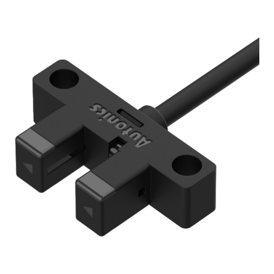
Autonics BS3-F1 Manual del producto - Página 2
Navegue en línea o descargue pdf Manual del producto para Accesorios Autonics BS3-F1. Autonics BS3-F1 3 páginas. Groove-depth 6.5 mm photomicro sensors

Ordering Information
This is only for reference, the actual product does not support all combinations.
For selecting the specified model, follow the Autonics website.
BS
3
-
❶
1
❶ Appearance
F
K
L
R
U
Cautions during Installation
• Refer to the table below when installing the sensor with screws. Purchase screws and
washers separately.
Screw
Spring washer
Flat washer (small round)
M2
Use
Ø 4.3 mm
M3
Use
Ø 6 mm
• In case of F and R type, as shown below, make sure that the bottom of the product
and the mounting surface are in direct contact with each other.
Proper installation
❷
-
❸
❷ Indicator
M: Turns ON under the light received condition
R: Turns ON under the light interrupted condition
❸ Control output
No mark: NPN open collector output
P: PNP open collector output
Tightening torque
0.15 N m
0.49 N m
Improper installation
Connections
For wiring, refer to the table below.
Color
Function
Brown + V
Black
Light ON (OUT 1)
White
Dark ON (OUT 2)
Blue
0 V
Brown
LOAD
Black
LOAD
NPN
White
Blue
■ Surge
Be sure to remove the surge before using the product.
When the surge occurs in the power lines, connecting the TVS diode (TVS) and capacitor (C)
to protect your device.
Brown
TVS
C
Blue
Circuit
■ NPN open collector output
VCC
LOAD
LOAD
OCP
SCP
OCP
SCP
Max. 50 mA
• OCP (over current protection circuit), SCP (short circuit protection circuit)
• If short-circuit the control output terminal or supply current over the rated specification,
normal control signal is not output due to the protection circuit.
• The operation indicator (red) flashes when the overcurrent or short occurs in the circuit.
Operation Timing Chart
Indicator turns ON under light
Model
received condition
Received
Received light
Interrupted
Operation
ON
indicator
OFF
Light
ON
ON
Transistor
output
OFF
ON
Operation
indicator
OFF
Dark
ON
ON
Transistor
output
OFF
Brown
Black
PNP
White
LOAD
LOAD
Blue
• TVS diode
V
(reverse stand-off voltage): 30 to 35 VDCᜡ
RWM
P
(power dissipation): ≥ 6.5 W
D
• Capacitor
Capacitance: 0.1 to 1 uF
■ PNP open collector output
VCC
Max. 50 mA
OCP
SCP
VCC
OCP
SCP
LOAD
LOAD
Indicator turns ON under light
interrupted condition
Received
Interrupted
ON
OFF
ON
OFF
ON
OFF
ON
OFF
