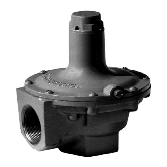
Emerson 289 Series Manual de instrucciones - Página 6
Navegue en línea o descargue pdf Manual de instrucciones para Unidad de control Emerson 289 Series. Emerson 289 Series 11 páginas.

289 Series
Warning
!
Avoid personal injury or property
damage from sudden release of
pressure or explosion of accumulated
gas. Before starting disassembly:
• Isolate the relief valve from line
pressure and
• Release trapped pressure from the
valve body and pressure line.
Type 289 A
All key numbers are shown in Figure 6.
1. Loosen the hex nut (key 11) and
unscrew the adjusting screw (key 6) to
relieve spring compression.
2. Unscrew the machine screws (key 8) and remove
the spring case (key 2), the spring seat (key 4),
the spring (key 7), the diaphragm head (key 3) and
the diaphragm (key 5).
3. Inspect the diaphragm and seating surfaces for
damage or wear and replace parts as
necessary. To remove the orifice (key 10)
unscrew it from the body.
4. Reinstall the orifice, the diaphragm, the
diaphragm head, the spring and the spring seat.
5. Reattach the spring case using the machine screws.
6. If a new spring with a different range is installed,
stamp the spring case with the new spring range.
7. Adjust the spring compression according to the
procedures outlined in the Startup section.
Type 289U
All key numbers are shown in Figure 7.
1. Loosen the hex nut (key 11) and
unscrew the adjusting screw (key 6) to
relieve spring compression.
2. Unscrew the machine screws (key 8) and
remove the spring case (key 2), the spring
seat (key 4), the spring (key 7) and the
diaphragm assembly (key 5).
3. Inspect the diaphragm assembly and seating
surfaces for damage or wear and replace
parts as necessary.
4. Reinstall the diaphragm assembly, the spring
and the spring seat.
6
บริ ษ ั ท เอดี ด ี เฟอร์ เ นส จ ำกั ด
ADD FURNACE CO.,LTD.
44 ซอยบรมราชชนนี 70 ถนนบรมรำชชนนี แขวงศำลำธรรมสพน์ เขตทวี ว ั ฒ นำ กรุ ง เทพฯ 10170
โทร: 02-888-3472 โทร: ออกแบบ
08-08-170-170
:
https://www.add-furnace.com E-mail:
แฟกซ์ : 02-888-3258
5. Reattach the spring case using the
machine screws.
6. If a new spring with a different range is installed,
stamp the spring case with the new spring range.
7. Adjust the spring compression according to the
procedures outlined in the Startup section.
Type 289L
All key numbers are shown in Figure 8.
1. Remove the closing cap (key 14) and the
gasket (key 15) and then unscrew the adjusting
screw (key 6) to relieve spring compression.
2. Unscrew the machine screws (key 8) and then
remove the spring case (key 2), the spring (key
7) and the diaphragm assembly (key 5).
3. Inspect the diaphragm and seating surfaces for
damage or wear and replace parts as
necessary. To remove the orifice (key 10),
unscrew it from the body. Check the pitot tube in
the diaphragm assembly for blockage and
remove any foreign material that might impair
proper operation of the relief valve.
4. Reinstall the orifice, the diaphragm assembly
and the spring.
5. Reattach the spring case using the
machine screws.
6. If a new spring with a different range is installed,
stamp the closing cap with the new spring range.
7. Adjust the spring compression according to the
procedures outlined in the Startup section and
then reinstall the closing cap and gasket.
Types 289HH and 1 NPT 289H
All key numbers are shown in Figure 9.
1. Loosen the hex nut (key 11) and then
unscrew the adjusting screw (key 6) to relieve
spring compression.
2. Unscrew the machine screws (key 8) and remove
the spring case (key 2), the spring seat (key 4)
and the spring (key 7).
3. Unscrew the hex nut (key 24) and remove the
lower spring seat (key 17), the diaphragm
head (key 3) and the diaphragm (key 5).
4. Unscrew the machine screws (key 29) and then
remove the stem guide assembly (key 31) and
attached parts from the valve body (key 1).
