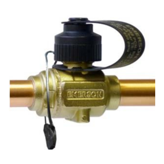
Emerson Alco Controls CVE-M06 Instrucciones de uso
Navegue en línea o descargue pdf Instrucciones de uso para Unidad de control Emerson Alco Controls CVE-M06. Emerson Alco Controls CVE-M06 7 páginas. Ball valves

G e n e r a l i n f o r m a t i o n :
The CVE/CVS series of Bi-directional Ball valves are
designed for general use in isolating suction, discharge
and liquid line pipe-work during maintenance
shutdown periods.
S a f e t y i n s t r u c t i o n s :
• Read
installation
instructions
Failure to comply can result in device failure,
system damage or personal injury.
• It is intended for use by persons having the
appropriate knowledge and skill.
• Before attempting to install the valve, make sure
pressure in system is brought to and remains at
atmospheric pressure.
• Do not release any refrigerant into the
atmosphere.
• Do not use any other fluid media without prior
approval of Emerson. Use of fluid not listed
could result in change of hazard category of
product and consequently change of conformity
assessment
requirement
accordance with European pressure equipment
directive 97/23/EC.
• The attached strap (Fig. 3) contains important
valve data. Do not remove because of warranty
and traceability reasons.
• Do not connect on CVS Schrader connection any
safety pressure switches or other control devices
M o u n t i n g l o c a t i o n :
• The CVE/CVS valve may be installed in any
position which allows access to remove the stem
cap. The valves are bi-directional.
• Locate the CVE/CVS as close as possible to the
section of pipe-work to be isolated. This will reduce
the amount of refrigerant to be recovered during
future maintenance of the system.
T e c h n i c a l D a t a :
Type:
Connection, DN
Max. working pressure PS
Factory test pressure
Medium temperature TS
Fluid group acc. PED
Refrigerant:
Material
Hazard category: PED 97/23/EC
Marking
Emerson Climate Technologies GmbH
Holzhauser Str. 180 I 13509 Berlin I Germany
Ball Valves Series CVE / CVS
I n s t a l l a t i o n :
• Do not remove seal caps until ready for installation.
The seal caps should be removed with care to avoid
damaging the connections.
• For CVS version do not mount schrader valve and
cap before brazing.
• For panel mounting see dimension of holes in Fig. 4.
B r a z i n g :
thoroughly.
Warning:
Ensure valve is in the fully open position before
brazing (see Fig. 2a). Failure to do so could cause
damage to internal components.
• Perform and consider the brazing joint as per
EN 14324.
• Before and after brazing clean tubing and brazing
joints.
• Minimize vibrations in the piping lines by appropriate
solutions.
• To avoid oxidization, it is advised to purge the system
with an inert gas such as nitrogen while brazing.
• Do not exceed the max. body temperature of 120
for
product
in
°C!
• To avoid overheating it is advised to make the joint at
one end cool the device completely before repeating
the procedure on the other end connection.
• For CVS version install schraeder valve and
schraeder valve cap after cooling down of the ball
valve.
P r e s s u r e T e s t :
After completion of installation, a pressure test must
be carried out as follows:
̵ according to EN 378 for systems which must
comply with European pressure equipment
directive 97/23/EC.
̵ to maximum working pressure of system for other
applications.
CVE-... /CVS-...
1/4" (6 mm) ... 7/8" (22 mm)
–40°C ... +120°C
www.emersonclimate.eu
Operating instruction
60 bar
66 bar
II
CO
2
CW617N
not applicable
Date: 09.02.2015
W a r n i n g :
• Failure to do so could result in loss of refrigerant
and personal injury.
• The pressure test must be conducted by skilled
persons with due respect regarding the danger
related to pressure.
T i g h t n e s s T e s t :
Conduct a tightness test according to EN 378-2 with
appropriate equipment and method to identify
leakages of external joints. The allowable leakage rate
must
be
according
system
specification.
O p e r a t i o n :
• The Valve has a built-in stop for the stem and
opening/closing of the valve is clearly indicated as
shown in Fig. 3. Open Valve is shown in Fig. 2a and
closed valve in Fig. 2b.
Note: Never leave the ball position as shown in
Fig. 2c otherwise seat leakage can occur.
• To avoid operation by unauthorized person's valve
can be equipped with a sealable cap which is
available as accessory (see Fig. 5).
• The plastic cap is equipped with an O-Ring. Do not
use any tool to mount the cap. Cap must be closed
hand tight only.
Warning:
If the valve is installed in hot gas discharge line, the
valve
has
hot
surface
temperature
operation of system or short after off-cycle.
S e r v i c e / M a i n t e n a n c e :
• Before starting repair work the internal R744
pressure has to be reduced gradually to atmospheric
(not more than 1 bar/min).
CVE(S)_OI_ML_R02_864199.docx
manufacturer's
during
