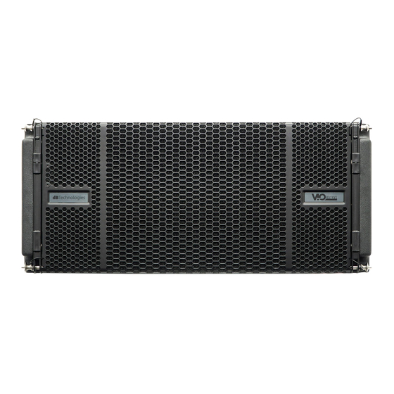
dBTechnologies VIO L1610 Manual de inicio rápido - Página 5
Navegue en línea o descargue pdf Manual de inicio rápido para Sistema de altavoces dBTechnologies VIO L1610. dBTechnologies VIO L1610 7 páginas. Symmetrical active 3-way line array with coaxial driver

4) First switch on for line-array setup
The DIGIPRO
G4®
amplifier of VIO L1610 is controlled
by a powerful DSP. All the connections and controls
are in the rear amplifier control panel:
VIO L1610
www.dbtechnologies.com
1 – Balanced audio input and output link
2 – High Pass Filter
3 – RDNet Data In / Data out
4 – DSP PRESET rotary switches (Speaker
coupling/High frequency compensation)
5 – Status LEDs (Limiter, Signal, Mute/Protection,
Ready)
6 – Control LEDs (Link, Active, Remote preset Active)
7 – Mini B-type USB port for firmware updating
8 – Auto-range Mains Input
9 – Mains link output
10 –Mains fuse
11 – System test
WARNING
The fuse is factory set for
If it is necessary to change the fuse to
1.
Turn off the power and disconnect the speaker from
any cable.
2.
Wait 5 minutes.
3.
Substitute the fuse with the correct one supplied.
a)
Once you have properly set up the mechanical
line-array configuration (see also the VIO L1610
complete user manual and accessories instructions for
further information), connect the audio input (1) of the
first module of the array. Then connect the useful link
audio output (1) to other VIO L1610 modules, for the
connection of all the line-array elements. Set HPF filter
(11).
b)
Check the rear panel
reference label for a proper
DSP regulation in line array.
Please note that this kind of
configuration can be set and
modified also by the use of
remote
controller (RDNet Control 2
or RDNet Control 8) and
software
Network).
information see the chapter
5.
In this rear label ("PRESETS")
you can find the suggested
position of rotary switches (4)
for each type of installation
(Speakers Coupling positions
and
Compensation).
settings are the main acoustic
corrections to create the
proper coupling between the
elements of your line-array,
in order to obtain the best
coverage conditions.
In particular, the "SPEAKER
COUPLING"
mainly on low frequencies, and it can be set in 6
positions, depending on the number of elements of
line-array.
5
info@dbtechnologies‐aeb.com
220-240V~
(dBTechnologies
For
this
High
Frequency
These
rotary
acts
420120324Q REV.1.0
operation.
100-120V~
range:
