dbx 263A Manual de instrucciones - Página 5
Navegue en línea o descargue pdf Manual de instrucciones para Equipos de grabación dbx 263A. dbx 263A 8 páginas. De-esser

MODEL 263A
To install two units side-by-side
-6
-4
-3
-2
-1
2.5k
Hi-Z MIC
INPUT
ON
1.8k
4k
800Hz
8kHz
FREQUENCY
R
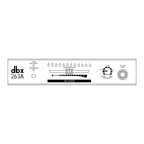
Figure 4: Rack Mounting Two 263A Units
You will need:
1
joiner assembly
(joiner, joiner side pieces)
1
reinforcing plate
2
rack ears
1
3/32Ó Allen wrench
1
Phillips screwdriver (not included)
4
pan head Phillips screws
4
flat head countersink screws
NOTE: The optional Accessory Kit includes the tools and hardware listed above, except as noted.
A. Remove the joiner assembly from the Accessory Kit. Note how the joiner side pieces are held
captive by the joiner before you separate them. This is important when it comes time to join
the units together. Now separate the joiner side pieces from the joiner by turning the thumb-
screw counterclockwise.
B. At this time you will need to designate a ÒLeftÓ and a ÒRightÓ unit.
C. With the left unit facing you, loosely attach a rack ear to the left side of the unit with two pan
head Phillips screws. On the right side of the unit, place a joiner side piece into the extruded
channel so the holes in the unit align with the holes in the joiner side piece - countersink side
up. Secure the joiner side piece with two countersink screws.
NOTE: If this is the first time the rack ear has been installed, you will be cutting threads
as you drive the screws. This is normal.
D. Repeat step C with the ÒRightÓ unit; swapping right for left with regard to the rack ear mounting
and left for right with regard to the joiner side piece mounting.
E. Place the Left and Right units on a flat surface, rear facing, so the joiner side pieces are
approximately 2Ó apart. Take the joiner assembly and loosen the thumbscrew so the sliding
catches clear the joiner side-piece cut-outs. Now place the joiner assembly against one of the
units with the side piece so it lays flush. (The joiner assembly should be positioned so the
thumbscrew is accessible from the rear of the unit.)
OPERATION MANUAL
HIGH
FREQUENCY
-20 -18 -16 -14 -12 -10
-8
GAIN REDUCT
BROADBAND
263A
MORE
DE-ESSE
OPERATION MANUAL
While holding the joiner assembly in position, slide the other unit over so it mates flush with
the joiner assembly and turn the screw clockwise until it is snug. Do not over-tighten. Both
units should now be secured together.
F. Make sure everything is aligned, and tighten the screws on each of the two rack ears.
NOTE: For installations where the two units will be subjected to physical stress (e.g.
portable operations), a small OPTIONAL reinforcement plate is included. See steps G
through I. If you donÕt wish to use the reinforcing plate, skip the following steps.
G. Turn the two units so that the back faces you. Remove the four rear cover screws nearest the
joiner knob.
H. Place the reinforcing plate over the joiner knob so that the four screw holes line up.
I. Replace the four screws, using the slightly longer screws provided in the Accessory Kit.
¨
PROFESSIONAL PRODUCTS
