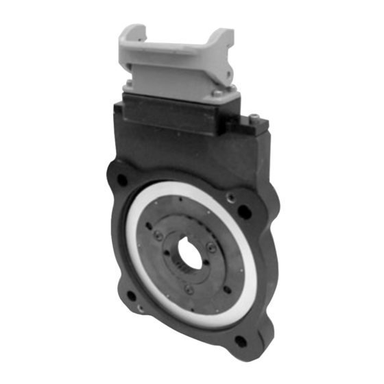
DYNAPAR NorthStar WIND 56 Manual de instrucciones - Página 10
Navegue en línea o descargue pdf Manual de instrucciones para Instrumentos de medida DYNAPAR NorthStar WIND 56. DYNAPAR NorthStar WIND 56 12 páginas. Magnetoresistive encoder for pitch control unit applications

2.3 Electrical Installation
Electrical connections are made to the sensor module through a standard 1/2 inch NPT liquid tight flexible
conduit. The nipple length may be changed to extend the outlet box if desired. Interconnection cable recom-
mendations are as follows: stranded copper, 22 through 16 gage, braided or foil with drain wire shielding
0.05 µF maximum total mutual or direct capacitance, outer sheath insulated. Shrink tubing may be placed
over any wires without insulation. For lengths over 100 feet, use 18 gage or larger, to a maximum of 1000
feet. If shielded twisted pair wire is used, do not cross channels. Keep each pair of complementary channel
outputs together in a single twisted pair (e.g., A and A complement).
CAUTION!
Reversing power and common will not damage the unit.
However, applying power to any of the sensor outputs
may cause damage.
Table 1. Signal Coding Table
Connector Pin
Signal
Common
B
A
Z *
No Connection
Vcc (5-15 VDC)
/B
/A
/Z *
Shield
+1.800.873.8731
©DYNAPAR
Page 10
NorthStar WIND 56 Instruction Manual
1
2
3
4
5
6
7
8
9
10
The shield in the sensor module is isolated from the frame of the
encoder for maximum noise immunity. The shield wire or pin should
be connected to the shield of the cable and that of the drive or other
receiving device.
702820-0001 Rev. C
NOTE
June 2012
