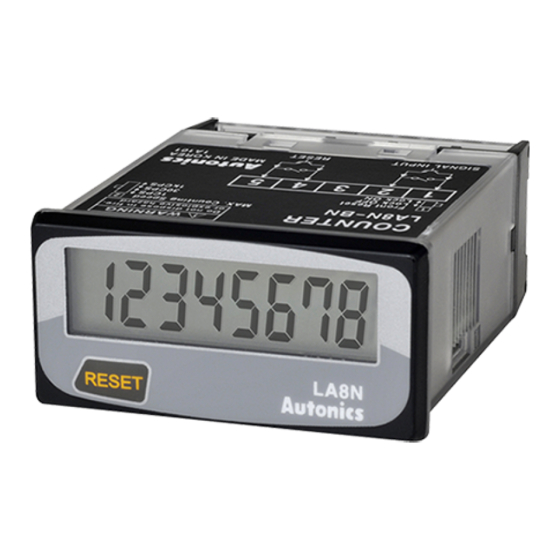
Autonics LA8N Series Manual del producto - Página 3
Navegue en línea o descargue pdf Manual del producto para Timer Autonics LA8N Series. Autonics LA8N Series 4 páginas. Lcd digital counters (indicator)
También para Autonics LA8N Series: Manual de inicio rápido (3 páginas), Manual (4 páginas)

DIP Switch Setting
• How to change the settings: power OFF → change settings → power ON →
press [RESET] key or input RESET signal (≥ 20 ms) to the
external terminal.
■ SW1
• Set the enable or disable [RESET] key on the front panel.
Front
SW1
1
■ SW2
• Set the max. counting speed of the no-voltage / voltage input models.
Front
SW2
2
■ SW3
• Set the position of decimal point.
• Detach the case first and change the SW3 setting. See the 'Detach the Case.'
Front
+
CR2477
3V
Counting Operations
■ Count up, count down, count up/down operation
H
SIGNAL
INPUT
L
A
UP /
H
DOWN
L
2
1
1
0
0
Counting
-1
• SIGNAL INPUT: counting input, UP / DOWN: counting command input
• UP / DOWN = in case of L, count up
UP / DOWN = in case of H, count down
• A should be over 20 ms of width. If A is below that of it, causing a possible counting error.
■ Count up operation
H
RESET
L
SIGNAL
H
INPUT
L
99999998
4
Counting
3
2
1
0
Setting
Use [RESET] key
Use (defaults)
1
Not used
1
Setting
Max. counting speed
2
1 kcps (defaults)
2
30 cps
2
1 cps
Setting
Decimal point
0 (defaults)
0.0
0.00
0.000
A
1
0
-1
-2
99999999
1
0
Input Connections
■ No-voltage input
• Solid-state input
Sensor
(NPN open collector output)
12 - 24 VDCᜡ
SIG. INPUT
OUT
RESET
• Do not supply the power to the terminals no. 1, 4.
The input terminal circuit can be broken, and a malfunction can occur.
• Terminals no. 2, 5 are connected inside.
• For Backlight model, the input terminals are no. 1, 3, and the GND terminal is no. 2.
• Contact input
Counter
3 VDCᜡ
560 kΩ
SIG. INPUT
1.2 kΩ
1.2 kΩ
RESET
0V
• Use reliable contacts enough to flow 3 VDCᜡ 5 ㎂ of current.
• For Backlight model, the input terminals are no. 1, 3, and the GND terminal is no. 2.
■ Voltage input
• Solid-state input
Sensor
(PNP open collector output)
Counter
12 - 24 VDCᜡ
SIG. INPUT
20 kΩ
OUT
RESET
• For Backlight model, the input terminals are no. 1, 3, and the GND terminal is no. 2.
• Contact input
Counter
SIG. INPUT
20 kΩ
4.7 kΩ
RESET
4.5 - 30 VDCᜡ
• Use reliable contacts enough to flow 3 VDCᜡ 5 ㎂ of current.
• For Backlight model, the input terminals are no. 1, 3, and the GND terminal is no. 2.
Counter
3 VDCᜡ
560 kΩ
1.2 kΩ
1.2 kΩ
3 VDCᜡ
560 kΩ
4.7 kΩ
3 VDCᜡ
560 kΩ
