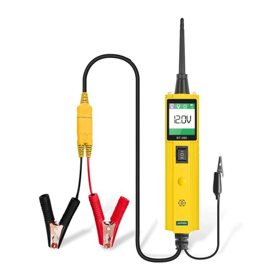
Autool BT 260 Manual del usuario - Página 2
Navegue en línea o descargue pdf Manual del usuario para Equipos de prueba Autool BT 260. Autool BT 260 7 páginas. Electric system tester

Table of Contents
1. SAFETY PRECAUTIONS AND WARNINGS............................................................ 2
2. USING THE TEST TOOL ......................................................................................... 2
2.1 TOOL DESCRIPTION ............................................................................................ 2
2.2 SPECIFICATIONS ............................................................................................ ..... 3
2.3 ACCESSORIES INCLUDED .................................................................................. 3
2.4 GENERAL DESCRIPTION ......................................................................................3
2.5 POWER ...................................................................................................................3
2.6 QUICK S ELF -T EST ............................................................................................. 4
2.7 CIRCUIT BREAKER ................................................................................................4
2.8 WORK MODE ..........................................................................................................4
3. TEST APPLICATIONS................................................................................................6
3.1 VOLTAGE & POLARITY TESTING ......................................................................... 6
3.2 CONTINUITY TESTING .......................................................................................... 6
3.3 SIGNAL CIRCUIT TESTING ................................................................................... 6
3.4 ACTIVATING COMPONENTS IN YOUR H AND ..................................................... 7
3.5 TESTING T RAILER LIGHTS AND CONNECTIONS ...............................................8
3.6 ACTIVATING COMPONENTS IN T HE VEHICLE ................................................... 8
3.7 ACTIVATING COMPONENTS W /G ROUND ......................................................... 9
3.8 CHECKING FOR B AD G ROUND CONTACTS ......................................................9
3.9 FOLLOWING & LOCATING SHORT CIRCUITS ..................................................... 9
3.10 R ED /GREEN POLARITY LED ........................................................................... 10
4. TEST TOOL SPECIFICATIONS................................................................................ 10
5. TEST TOOL KNOW-HOW......................................................................................... 11
6. WARRANTY AND SERVICE..................................................................................... 11
6.1 LIMITED O NE Y EAR WARRANTY ...................................................................... 12
6.2 SERVICE PROCEDURES ..................................................................................... 12
1
Safety Precautions and Warnings
To prevent personal injury or damage to vehicles and/or the test tool, read this instruction
manual first and observe the following safety precautions at a minimum whenever working
on a vehicle:
•
Always perform automotive testing in a safe environment.
•
Wear safety eye protection that meets ANSI standards.
•
Keep clothing, hair, hands, tools, test equipment, etc. away from all moving or hot engine
parts.
•
Operate the vehicle in a well ventilated work area: Exhaust gases are poisonous.
•
Put blocks in front of the drive wheels and never leave the vehicle unattended while
running tests.
•
Use extreme caution when working around the ignition coil, distributor cap, ignition wires
and spark plugs. These components create hazardous voltages when the engine is
running.
•
Put the transmission in PARK (for automatic transmission) or NEUTRAL(for manual
transmission) and make sure the parking brake is engaged.
•
Keep a fire extinguisher suitable for gasoline/chemical/ electrical fires nearby.
•
Don' t connect or disconnect any test equipment while the ignition is on or the engine is
running.
•
Keep the tool dry, clean, free from oil/water or grease. Use a mild detergent on a clean
cloth to clean the outside of the test tool, when necessary.
•
When the power switch in the tool is depressed battery current/voltage is conducted
directly to the tip which may cause sparks when contacting ground or certain circuits.
Therefore the tool should NOT be used around flammable such as gasoline or its vapors.
The spark of an energized tool could ignite these vapors. Use the same caution as you
would when using an arc welder.
Using the Test Tool
Tool Description
① Probe Tip - Contacts the circuit or component to be tested.
② Head Lights - Illuminates dark work areas or work areas at night. .
③ Red/Green Polarity Indicator - Identifies positive, negative or contacting
a positive circuit. The GREEN Indicator lights when the Probe Tip
is contacting a negative circuit.
④ LCD Display -Indicates test results.
⑤ Circuit Breaker Reset - Resets the tool when the Circuit
Breaker is tripped。
⑥ Power Switch - Allows you to conduct a positive or negative
battery current to the tip for activating and testing the function
of electrical components.
2
