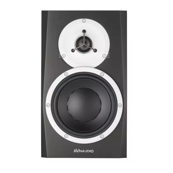
Dynaudio BM 5A COMPACT Manual del usuario - Página 8
Navegue en línea o descargue pdf Manual del usuario para Altavoces Dynaudio BM 5A COMPACT. Dynaudio BM 5A COMPACT 12 páginas. Two-way active nearfield monitor
También para Dynaudio BM 5A COMPACT: Manual del usuario (11 páginas), Manual del usuario (11 páginas)

1R2. Power :nR:ff switchR%C Power In
]efore switching onF maRe sure Mains boltage
matches your areas Mains boltage specification0
"eplace fuse only with the fuseLtype marRed on
the rearLpanel laNel0
3. Balanced analog Input
Mudio Input is via a female cd" connector0 The
Input is electronically Nalanced with following
connections0 The connections are printed on
the rear for easy reference0
If your signal source is unNalancedF usually the
unused pin is connected to ground0 This is
normally done inside the connecting caNle0
Special adaptors Hnot suppliedI can Ne Nought
that converts Slr input to single ended ">M type
input0 :or Nest result use only good Yuality
screened caNles and connectors0
Switches
On the rear of the monitor you will find ;
switches for setting up the monitor for optimum
performance in different acoustic environments0
^ach switch is eSplained in the following0
4. Uigh Pass filter switch
This switch sets the lower cutLoff freYuency of
the monitor0 It is used to match the monitor to a
suNwoofer0 You can select Netween =P5z or
EP5z cLover0 :lat is used in case you do not
use a suNwoofer to assist your monitors0 When
used with a suNwoofer it is recommended to
use either =P5z or EP5z filterF thus allowing a
higher undistorted soundLpressure level0
6
SETTIND AP
5. Level trim
Vse this switch to match the sensitivity of the
]M ;M >ompact monitor to your source0
5ighLoutput source
If your source has a high OutputF set the switch
to the L!P position to reduce the sensitivity Ny
!Pd]0
dowLoutput source
If your source has low outputF set to e9 position
to gain 9d] more sensitivity0
6. LF
This switch controls the Nass gain level using
shelfLtype ^f0 The level can Ne set to e1d]F
0
Pd] or L1d]0
+
This filter is used to adXust for the proSimity of
NoundariesF so if positioned close to wall or
-
cornerF use the L1d] setting0 If positioned far
from walls use the e1d] or P positionF
depending on other eYuipmentF and personal
taste0
7. MF
This switch sets a notch filterF used to
compensate for the acoustic effect of a console0
Such placement usually results in a response
peaR in lower midrange0 The M: switch
activates a Nell shaped notch filterF which can
compensate0 Vse either the L1 or the L9d]
setting0 You may eSperiment finding the settingF
which provides the flattest response0
8. UF
This switch controls the TreNle level and it is
used to match the high end of the monitor to
your other electronic eYuipmentF and your
acoustical environment0 Vse the setting
providing the preferred timNre0 If the sound is
too Nrightg try to set to L!d] to reduce treNle Ny
!d]0 If too dull soundF use e!d] setting to raise
the treNle Ny !d]0
