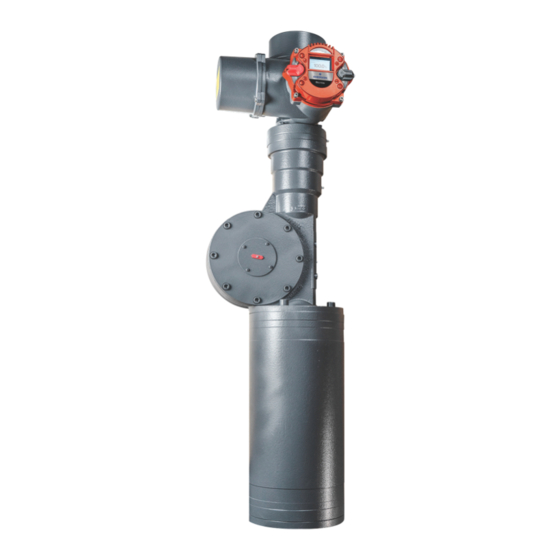
Emerson Bettis RTS Manual de instalación, uso y mantenimiento - Página 6
Navegue en línea o descargue pdf Manual de instalación, uso y mantenimiento para Equipamiento industrial Emerson Bettis RTS. Emerson Bettis RTS 18 páginas. Extension board for modbus rtu
También para Emerson Bettis RTS: Manual de servicio (18 páginas), Manual de instalación, uso y mantenimiento (16 páginas), Manual de instalación, uso y mantenimiento (18 páginas), Manual de instalación, uso y mantenimiento (16 páginas)

Section 2: Connection
November 2021
Section 2: Connection
Depending on the order, there are the following connection options:
•
•
2.1
Standard Design
PROFIBUS cables connect via the input/output board in the terminal compartment for
the customer's plug connector for the actuator. The PROFIBUS connection is thus, like
the other electrical connections, plug- connectable both for power and signals. When
the connecting plug is unplugged, the connection within the line for the PROFIBUS
is maintained, i.e., the connecting plug can be unplugged during operation without
interrupting the communication to other bus subscribers.
NOTE
The PROFIBUS has to be terminated at the end of the line. This active bus termination can
be made on the input/output board. The supply for the terminating resistors, however, is
carried out from the actuator, i.e., with the plug connector unplugged, the bus termination
is not supplied. To avoid such problems, we recommend terminating the bus separately
with an active bus termination.
If the PROFIBUS is a single-channel design, the PROFIBUS cables connect on Channel I, and
with a dual- channel design (option: redundant), Channel I and Channel II are used.
2.1.1
Terminal Board (Provided by customer)
The terminal board is located in the terminal compartment for the customer's plug
connector beneath the top cover.
Figure 1
2
Installation, Operation and Maintenance Manual
Standard design: via terminal board
Explosion-proof design: via terminals
Terminal Board
VCIOM-15590-EN Rev. 0
Connection
