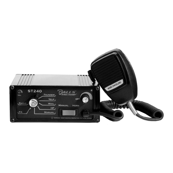
Galls Street Thunder ST240 Manual de instrucciones de instalación y funcionamiento - Página 4
Navegue en línea o descargue pdf Manual de instrucciones de instalación y funcionamiento para Amplificador Galls Street Thunder ST240. Galls Street Thunder ST240 12 páginas. Siren amplifier

Wire Size and Termination
Electrical connections to this unit are made through the green 12-terminal
connector located in the rear of the unit (See below - Part # CPSS-153).
Examine the charts below to determine the proper gauge of the wire to use. Please
review the following recommendations when making your electrical connections:
• For safety and reliability we highly recommend that you always use both Power
terminals (1 & 2) and both Ground terminals (3 & 4).
• Use only high quality crimp connectors. Make sure all connections are tight.
• Minimize the number of splices to reduce voltage drop.
• Route wiring to prevent wear, overheating, and interference with air bag
deployment.
• Use grommets and sealant when passing through compartment walls.
• Ground connections should be made directly to the negative of the vehicle
battery. Where not possible, only connect to substantial chassis components.
• Install and check all wiring before connection to vehicle battery.
• CAUTION: All wires should be rated for at least 125% of their maximum current
load. All wires connected to the positive terminal of the battery should be fused
at the battery for their rated load.
• Review the charts below that indicate the recommended wire gauge, based
upon the length of the wire run and the current that will pass through the wire.
WIRING GUIDE
Typical
Description
Terminal
Color
1
Power
2
Power
3
Ground
Black
4
Ground
Black
5
Speaker 1
Brown
6
Speaker 2
Brown
7
AUX In
Green
8
AUX Out
Orange
9
Radio Repeat
Blue
10
Radio Repeat
Blue
11
Backlighting
Yellow
12
Park/Kill Input
White
(Please note that this diagram references the connector with the siren UPSIDE-DOWN)
BATTERY
12V
20A
Fuse
1
2
3
4
WARNING: ENSURE CONNECTOR IS FULLY INSERTED & SCREWS LOCKED
Electrical Connections
Typical
(Please note that this is an upside-down view)
Current
Red
10A
20A
Total
Red
10A
10A
20A
Total
10A
4A
4A
3A
Current
3A
< 2.0A
0.1A
2.0-4.0A
0.1A
4.1-5.5A
0.1A
5.6-8.0A
0.1A
8.1-12.0A
Factory Horn
Factory
Horn
Relay
Speaker
5
6
7
8
9
(SIREN TOP)
-2-
CPSS-153
RECOMMENDED WIRE GAUGE
10'
20'
22 AWG
18 AWG
18 AWG
16 AWG
18 AWG
16 AWG
16 AWG
14 AWG
16 AWG
12 AWG
2 Way
Radio
10
11
12
SELECT
25'
18 AWG
16 AWG
14 AWG
14 AWG
12 AWG
POS
NEG
TONE
