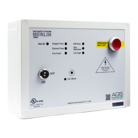
AGS Merlin 1500S Manual de uso e instalación - Página 7
Navegue en línea o descargue pdf Manual de uso e instalación para Control Panel AGS Merlin 1500S. AGS Merlin 1500S 8 páginas. Gas & ventilation interlock system
También para AGS Merlin 1500S: Manual de instalación y funcionamiento (12 páginas), Manual del usuario (12 páginas)

Merlin 1500S
Gas Interlock System
1500S Wiring Diagram
Mains Input 110-120VAC.
1.
Gas Solenoid Valve Power Output, 110-120VAC.
2.
Supply Fan 1 and 2 external pressure differential switch or current switch. VOLT FREE INPUT
3.
Extract Fan 1 and 2 external pressure differential switch or current switch. VOLT FREE INPUT
4.
BMS output contacts. Normally Closed, Common and Normally Open. Max.1A @ 120VAC.
5.
Remote EM Stop buttons and Fire Alarm input wired in series (purchased separately). VOLT FREE INPUT
6.
Methane, CO or LPG Detector, power supply and VOLT FREE INPUT (purchased separately).
7.
Fan Switch output (purchased separately). For wiring instruction see Fan Switch user manual.
8.
CO2 Monitor (purchased separately). VOLT FREE INPUT
9.
10. Permanent 12VDC output (Normally used to power a PM2 Current Monitor). 50A Max.
Rev: 03 Date: 08-01-18
Please note, Mains wires and low voltage wires
should not be run in the same conduit as per the
LOW VOLTAGE DIRECTIVE
User & Installation Manual
7
