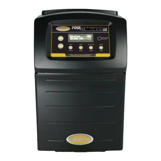
Jacuzzi 27844.01 Manual de instalación y funcionamiento - Página 8
Navegue en línea o descargue pdf Manual de instalación y funcionamiento para Filtro de piscina Jacuzzi 27844.01. Jacuzzi 27844.01 19 páginas. Domestic chlorine generating device

Section 2b – INSTALLATION
Electrical Connections
Autopilot recommends that a licensed electrician or certified electrical contractor perform the electrical connections.
DANGER: ensure that the electrical panel or filter pump circuit breaker is turned OFF before wiring this unit.
Your Commander III Model JC7 Control Box comes pre-wired from the factory for 230VAC (1.5 amps max draw) and can
also operate on 115 VAC, (3.0 amps max draw) at 50/60Hz. 1.8 m (6 ft.) of AC lead wires are provided with the unit and are
located on the bottom base plate of the control box along with the Cell, Tri-Sensor and optional ORP Interface connections.
Converting to 115VAC is accomplished by accessing the circuit board, rewiring, and attaching the included jumper as shown
below. Remove the cover (see page 12) to access and ensure that the Jumper Connections on the circuit board marked
"TRANSFORMER PRIMARY" are matched to the LINE IN voltage. Follow all state/local codes for electrical installations.
►An additional jumper is
provided with your
Installation Kit for 115VAC.
Location of the
Input Jumper Connections
Top terminals factory wired – do not disturb.
AC to PCB
#1
#2 #3 #4 #5 #6
Ground
Lugs
(Gr/Yel) (Br) (Bl)
Pool Pilot AC Line IN
Pump AC Line IN
AC LINE IN (Wiring diagram also located on inside of cover):
For 230 VAC; Brown (Br) = Line 1, Blue (Bl) = Line 2, Green w/Yellow Tracer (Gr/Yel) = Earth Ground
For 115 VAC; Brown (Br) = Line, Blue (Bl) = Neutral, Green w/Yellow tracer (Gr/Yel) = Earth Ground
The AC Line IN wiring is pre-set for connection to the LOAD SIDE of your time clock, electronic controller switch or relay to
work in conjunction with your circulation pump.
For control of your main circulation pump (single or two speed) through the Commander III Model JC7's Internal Relay, cut
and strip the pre-wired Line In wires, and jump #1 to #3 and #2 to #4 (Gr/Yel can be discarded). Route a new set of Pump AC
Line IN wires from the circuit breaker/electrical panel into #3, #4 and Pump Ground Lug. Connect Pump AC Line OUT to #5,
#6 and Pump Ground Lug. This relay is rated for 30-amp max. Ensure that the Line In and Line Out wire sizes are according
to electrical guidelines. Follow the menu program, pages 8 & 9, to program the Digital to your particular application. Ensure
that the Commander III Model JC7 Control Box is properly bonded to a grounding circuit.
. Each Cell Cord contains (2) Banana Plugs that attach to the (2) Banana Jacks on the bottom of the Control Box.
Cell Cord
Polarity does not matter. The other end of the cell cord has a three-position plug that connects to the cell in any direction. See
page 13 for service instructions.
. The Tri-Sensor Cord connects to the keyed 6-pin harness on the Control Box Base Plate. The opposite
Tri-Sensor Cord
end of the cord connects to the Tri-Sensor Assembly with a locking ring quick connect. Align the grove and keyway on the
connector and twist the locking ring to ensure a proper connection. Refer to the instructions on pages 12 & 14 for diagrams
and additional instructions.
. When an ORP Chemical Controller is interfaced to your Commander III Model JC7, the Chemical
ORP Connection
Controller will remotely control the sanitizer Output. Adjust the output level to 0% and connect the ORP controller to the 2-
pin connector on the Control Box Base Plate. When the ORP is activated, the output will indicate ON with the display
showing 0%.
WARNING: THE ORP CONNECTIONS ARE DRY CONTACT INPUTS, DO NOT ENERGIZE THESE
INPUTS! DAMAGE TO THE CONTROL BOX WILL OCCUR AND WILL VOID THE WARRANTY.
Control Box Connections
Power Circuit Board
Transformer
INNER CONTROL PANEL
AC L
ine IN
for F
ilter Pump
AC Line OUT
to Filter Pump
Pump
Ground
Lug
Internal Relay
Pump Ground Lug
Load wires out to Single Speed Pump
(or Brown to High Speed)
Pump AC Line OUT
TAB 10
TAB 9
TAB 8
TAB 7
230VAC
TAB 6
TAB 5
TAB 4
TAB 3
TRANSFORMER PRIMARY
230 VAC
FACTORY SETTING
Bonding
Lug
Relay trigger
Conduit
(to Low Speed) connector
provided
Pump conduit
5
TAB 10
TAB 9
TAB 8
115VAC
TAB 7
TAB 6
TAB 5
115VAC
TAB 4
TAB 3
TRANSFORMER PRIMARY
115 VAC
WIRING DIAGRAM
6-pin Tri-sensor
connector
Plug
AC
Plug
Line In
2-pin ORP
Plugs
Connector Connectors
CONTROL BOX BASE PLATE
Cell Cord
