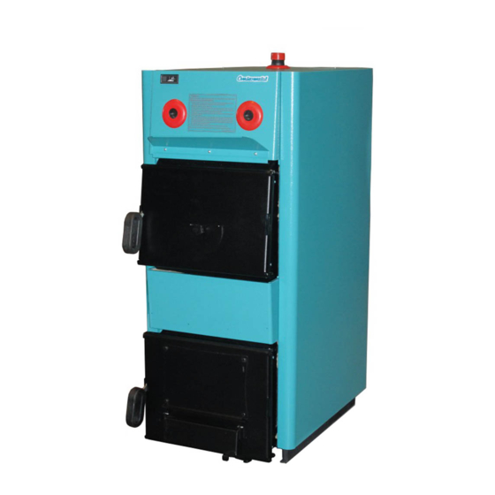
Centrometal EKO-CK P 25 Instrucciones técnicas - Página 8
Navegue en línea o descargue pdf Instrucciones técnicas para Caldera Centrometal EKO-CK P 25. Centrometal EKO-CK P 25 20 páginas. Hot water boiler
También para Centrometal EKO-CK P 25: Uso y mantenimiento (20 páginas)

Installation of casing
Figure 5. Installation of casing to boiler EKO - CK P
b5
b6
b3
b4
b1
b2
1.
Fasten insulation support (8) with screws 4,2 x 16 into wholes at the upper side of the
boiler body.
2.
Fix the lateral sides (2) and (3) on girders on the lateral sides of the boiler mount into
rectangular opening of the casing lateral sides (b1) and (b2), hook them up on casing
supports (8), and fix them with two screws on sheet metal 3.9 x 9,5 on the rear casing
supports (8).
The front upper casing side (5) has to be hooked up with hooks into rectangular
3.
openings of the lateral left and lateral right side of the casing (b5) and (b6), and fixed
with one screw on sheet metal 4,2 x 16 into the front casing support (8) through the
lateral side (2) and with one screw for sheet metal 4,2x16 into the front casing support
(8) through the lateral side (3).
The front bottom casing side (4) has to be hooked up with hooks into rectangular
4.
openings of casing lateral sides (b3) and (b4).
We insert the thermometer sensor at the front upper side of the casing (5) and pump
5.
thermostat sensor at the rear casing cover (9) into the probe at the upper side of the
boiler, and secure the sensors with wire delimiter supplied in the set (Detail Y).
6.
We position the front casing cover (6) on the groove of the front upper casing side, and
the rear casing cover (9) on the groove of the front casing cover (6).
7.
We hook the rear casing side (1) on the connecting pipe and fix it with 2 screws for
sheet metal 4,2 x 32 on the lateral side (2) and 2 screws for sheet metal 4,2 x 32 on the
lateral side (3).
8.
We fix the rear casing cover (6) from the upper side with 2 screws for the sheet metal
4,2 x 32 on lateral casing sides (2) and (3).
At the end, we fix the draught regulator protection (7) on the front upper casing side (5)
9.
on the prefabricated holes with three sheet metal screws 3,9 x 9,5.
10.
Finally, we take the base protection (10) and insert it under the boiler between the
supports holding the boiler.
8
9
C
6
B
B
X
B
B
8
A
A
1
2
B
B
5
3
7
A
A
A
4
10
C
8
(3.9x9.5)
A
(4.2x16)
B
(4.2x32)
C
Detail X
Technical instructions EKO-CK P
