Major tech MT740 Manual de instrucciones - Página 2
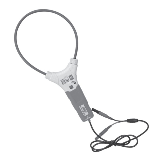
Navegue en línea o descargue pdf Manual de instrucciones para Instrumentos de medida Major tech MT740. Major tech MT740 2 páginas. Flexible trms clamp adaptor

1. Safety Information
International Safety Symbols
This symbol, adjacent to another symbol or terminal, indicates the user must refer to the manual
for further information.
This symbol, adjacent to a terminal, indicates that, under normal use, hazardous voltages may be
present
Double insulation
Safety Notes
Ÿ
Do not exceed the maximum allowable input range of any function
Ÿ
Do not use when instrument power is off.
Ÿ
Remove the battery if meter is to be stored for longer than 60 days.
Caution
Ÿ
Improper use of this meter can cause damage, shock, injury or death. Read and understand this
user manual before operating the meter.
Ÿ
Inspect the condition of the test coil and the meter itself for any damage before operating the
meter. Repair or replace any damage before use.
Ÿ
Use great care when making measurements if the voltages are greater than 25VAC RMS or
35VDC. These voltages are considered a shock hazard.
Ÿ
If the equipment is used in a manner not specified by the manufacturer, the protection provided
by the equipment may be impaired.
Ÿ
Do not operate meter while Low Battery warning is on. Replace batteries immediately.
2. Description
1. Flexible current coil
2. Range switch
3. Power switch
1
4. Analog voltage output cable
5. Power indication
6. Turn knob
2
3
4
3. Operation
AC Current Measurements
According to the power switch, turn on the instrument power
supply, insert the output line of the meter into the input end
of the high precision digital universal meter with AC voltage
measurement function. Pre estimate the size of the current, to
obtain the best output signal, to choose a good measurement
of gear. Single phase and then measured the ring into the
flexible coil, placed in the central position, and completely
closed. This can be converted to obtain the magnitude of the
current value.
4. Position Error of Clamp
Accuracy and position error assumes centralized primary conductor
at optimum position ,no external electrical or magnetic field, and
within operating temperature range.
Distance from
Optimum(mm)
5. Maintenance
Cleaning and Storage
Periodically wipe the case with a damp cloth and mild detergent; do not use abrasives or solvents.
If the meter is not to be used for 60 days or more, remove the battery and store it separately.
Battery Replacement
1. When the battery capacity is more than 2.5V, the power indicator light is green. When the battery
capacity is about less than 2.5V, the power indicator is red. Need to replace the battery in time.
2. Remove the Phillips head screw that secures the rear battery door
3. Open the battery compartment.
4. Replace two AAA batteries.
6
5. Secure the battery compartment.
6. Technical Specifications
5
Function
AC Current
50~400Hz
True RMS
Note:
Ÿ
Accuracy is given as ±(% of reading + counts of least significant digit) at 23°C±5°C, with relative
humidity less than 80%RH.
Ÿ
Output Noise: <5.5mV for each range.
Ÿ
Max. output voltage: 5.8V.
Ÿ
All scale, if the output voltage is greater than 3V, the results indicate that the measurement has
been out of range, not to be used as indicator assessment.
Flexible coil
Error
radius (mm)
A
35
1.0%
B
50
1.5%
C
60
2.0%
Range
Best Measurement
Output
Range
Voltage
30A AC
≤30.00A
100mV/A
300A AC
30.0A-300.0A
10mV/A
3000A AC
300A-3000A
1mV/A
VAC
3000A
1mV/A
10mV/A
300A
30A
100mV/A
1.0000
POWER ON
LOW POWER
VAC
A
B
C
Accuracy
± (3.0% + 5mV)
± (3.0% + 3mV)
± (3.0% + 3mV)
