Major tech MT474 Manual de instrucciones - Página 7
Navegue en línea o descargue pdf Manual de instrucciones para Equipos de prueba Major tech MT474. Major tech MT474 12 páginas. 690v voltage tester

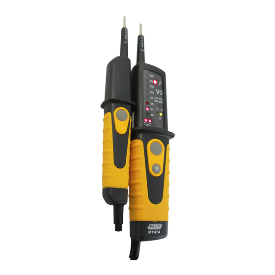
3. VOLTAGE TESTER DESCRIPTION
1 - Handle test probe - (L1)
2 - lnstrument test probe + (L2)
3 - Measurement point illumination
4 - LEDs for voltage display
5 - LED for single-pole phase test
6 - LED for low impedance test
7 - LED for left/right rotary field
4. EXPLANATION OF SYMBOLS
The voltage tester shows the following symbols:
DC
DC voltage
AC voltage
AC
DC voltage negative potential (DC)
Phase display from 100 to 690V - 50/60Hz when used as a
"single-pole" phase tester.
Continuity test symbol
Rotating field display clockwise
Rotating field display anticlockwise
Device for work to be performed with voltage present
Battery replacement symbol
8 - LED for continuity
9 - Low impedance switch (L2)
10 - Measurement point lighting
Button
11 - Battery case
12 - Low impedance switch (L1)
7
