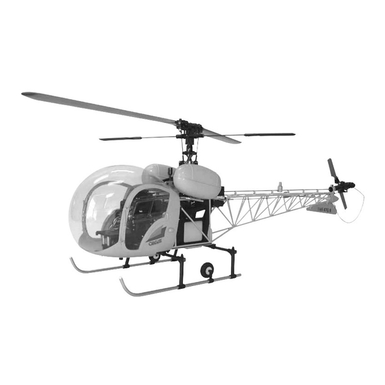
Century Helicopter Products CN1074 Manual - Página 5
Navegue en línea o descargue pdf Manual para Juguete Century Helicopter Products CN1074. Century Helicopter Products CN1074 15 páginas.

Updates to Steps in the Scale Mechanics Manual
Updates to Steps in the Scale Mechanics Manual
Updates to Steps in the Scale Mechanics Manual
Updates to Steps in the Scale Mechanics Manual
Updates to Steps in the Scale Mechanics Manual
The following Step numbers are referrenced from the steps in the main Scale Mechanics Manual.
STEP 1-3 Main Blade Grip Assembly
STEP 1-3 Main Blade Grip Assembly
STEP 1-3 Main Blade Grip Assembly
STEP 1-3 Main Blade Grip Assembly
STEP 1-3 Main Blade Grip Assembly
From parts bag 1: Install one Long Ball and one Short Ball into the Bell Mixer, insert the slide tube into the bell
mixer arm (Note: the oilite bearings are pre-installed
Note: the oilite bearings are pre-installed
Note: the oilite bearings are pre-installed) and secure onto the blade grip with one M3x16 Socket
Note: the oilite bearings are pre-installed
Note: the oilite bearings are pre-installed
Cap screw and M3x7 Flat washer. Install two M6x13 Ball Bearings into each end of the blade grip assembly.
Complete the second blade grip in exactly the same way.
STEP 1-4 Feathering Spindle & Blade Grips
STEP 1-4 Feathering Spindle & Blade Grips
STEP 1-4 Feathering Spindle & Blade Grips
STEP 1-4 Feathering Spindle & Blade Grips
STEP 1-4 Feathering Spindle & Blade Grips
From parts bag 1: Insert the Feathering Shaft into the head block, slide one M6x10 washer on each side of the
shaft. Install the blade grip (Note the direction of the bell mixer arm) followed by one M8x13 washer, one M6x12
Thrust Ball Bearing (install the first steel washer (large inside diameter) followed by the ball race, remember to
grease the ball race, followed by the second steel washer (smaller diameter ) and one M6 Locknut. Tighten the
locknut, using the glow plug socket wrench on one nut while holding theother with pliers, tighten the nuts until
both blade grips turn freely without any excessive end play.
STEP 1-7 Flybar, Paddles and Flybar Control Arms
STEP 1-7 Flybar, Paddles and Flybar Control Arms
STEP 1-7 Flybar, Paddles and Flybar Control Arms
STEP 1-7 Flybar, Paddles and Flybar Control Arms
STEP 1-7 Flybar, Paddles and Flybar Control Arms
The kit version is already pre-assembled, for referrence, using an available M3x12 Button Head Screw,
insert approximately half the length of the screw to form threads into the smaller, tapered ends of the
control arms and the control arm stand-offs. Assemble Pushrod A and press one ball link end onto each
double studded steel ball, making sure that pressure is applied from the side of the ball link with the Cen-
tury name. All ball links are designed to be installed in one direction only. While holding one flybar con-
trol arm, start threading the double studded steel ball. When it becomes difficult to turn with fingers, start
the control arm stand-off and use as a driver until tight. Complete the second flybar control arm.
Slide and center the Flybar through the seesaw arm assembly inserted from the bottom of the rotor head
block. Carefully look at Flybar Control Arm and notice that when installed correctly, the securing set
screw is on top. Loosely tighten the M4x5 Set Screws into the round aluminum inserts directly over the
flat spots that are already on the flybar. Using a ruler, check the distance between the end of the flybar
and the control arm and adjust until the lengths are the same. Remove one set screw at a time, apply
threadlock and tighten in place. Slide the Flybar Weight (Tip
and thread on the Flybar Paddle until all the threads are covered onto the flybar and align the paddles
parallel. Again using the ruler, rotate one paddle or the other to get equal distances, remember leading
edge of the paddles turn clockwise. Using two 3x3mm Set Screws secure the weights using threadlock.
STEP 6-1 Pushrod Setup & Adjustment
STEP 6-1 Pushrod Setup & Adjustment
STEP 6-1 Pushrod Setup & Adjustment
STEP 6-1 Pushrod Setup & Adjustment
STEP 6-1 Pushrod Setup & Adjustment
This helicopter is designed for a 46/50 size engine, as a result the following pushrod (end to end) measure-
ments are:
Pushrod
Pushrod
Pushrod
Pushrod
Pushrod
Washout Arm to Flybar Control Arm
Aileron Bellcrank to Swashplate
Bell Mixer to Swashplate (long)
Throttle Pushrod
Collective Pushrod
STEP 6-8 Assembly of ARF Main Blades
STEP 6-8 Assembly of ARF Main Blades
STEP 6-8 Assembly of ARF Main Blades
STEP 6-8 Assembly of ARF Main Blades
STEP 6-8 Assembly of ARF Main Blades
Main blades are 600mm, part number CN2324.
Main blades are 600mm, part number CN2324.
Main blades are 600mm, part number CN2324.
Main blades are 600mm, part number CN2324.
Main blades are 600mm, part number CN2324.
4
Tip
Tip
Tip: the flat end of the weight faces the paddle)
Tip
Code
Code
Code
Length
Length
Length
Code
Code
Length
Length
A
51mm
J
62mm
C
106mm
B
99mm
D
96mm
