IKEA LUFTIG Instrucciones de instalación y manual de uso y mantenimiento - Página 6

Navegue en línea o descargue pdf Instrucciones de instalación y manual de uso y mantenimiento para Campana de ventilación IKEA LUFTIG. IKEA LUFTIG 44 páginas. Exhaust hood
También para IKEA LUFTIG: Manual del usuario (12 páginas), Manual de instrucciones (28 páginas), Manual del usuario (12 páginas), Manual (16 páginas), Manual de instalación (24 páginas), Manual de instrucciones (40 páginas), Manual (16 páginas), Manual del usuario (28 páginas), Montaje (11 páginas), Instrucciones de instalación (4 páginas), Manual (24 páginas)
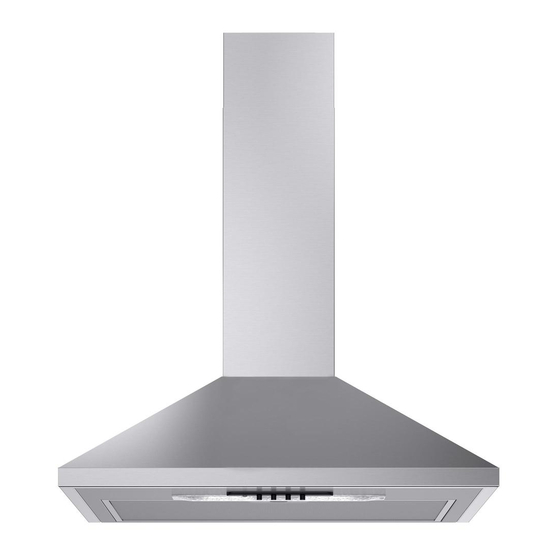
IKEA LUFTIG Instrucciones de instalación y manual de uso y mantenimiento
Cold Weather Installations
An additional back draft damper should be installed to minimize
backward cold air flow and a thermal break should be installed to
minimize conduction of outside temperatures as part of the vent
system. The damper should be on the cold air side of the thermal
break.
The break should be as close as possible to where the vent
system enters the heated portion of the house.
Makeup Air
Local building codes may require the use of makeup air systems
when using ventilation systems greater than specified CFM of air
movement. The specified CFM varies from locale to locale.
Consult your HVAC professional for specific requirements in your
area.
Venting Methods
Vent system can terminate either through the roof or wall. Use
7" (17.8 cm) or larger round vent with a maximum length of
50 ft (15.2 m) for vent system.
NOTE: Flexible vent is not recommended. Flexible vent creates
both back pressure and air turbulence that greatly reduce
performance.
Roof Venting
B
A
C
A. 7" (17.8 cm) round vent
through roof
(purchased separately)
B. Roof cap with damper
(purchased separately)
C. 24" (61.0 cm) min. above the
cooking surface
6
Wall Venting
B
A
C
A. 7" (17.8 cm) round vent out
the top and through the wall
(purchased separately)
B. Wall cap with damper
(purchased separately)
C. 24" (61.0 cm) min. above the
cooking surface
Calculating Vent System Length
To calculate the length of the system you need, add the
equivalent feet (meters) for each vent piece used in the system.
7" (17.8 cm) Round Vent System
Vent Piece
45° elbow
90° elbow
7" (17.8 cm) wall cap
3¹⁄₄" x 10" (8.3 cm x 25.4 cm)
to 7" (17.8 cm)
3¹⁄₄" x 10" (8.3 cm x 25.4 cm)
to 7" (17.8 cm) 90° elbow
Example vent system
7" (17.8 cm) round
90˚ elbow
2 ft (0.6 m)
Maximum Recommended Length
1 - 90° elbow
1 - wall cap
8 ft (2.4 m) straight
Length of 7" (17.8 cm) system
Round
2.5 ft
(0.8 m)
5.0 ft
(1.5 m)
0.0 ft
(0.0 m)
4.5 ft
(1.4 m)
5.0 ft
(1.5 m)
Wall cap
6 ft (1.8 m)
= 50 ft (15.2 m)
= 5.0 ft (1.5 m)
= 0.0 ft (0.0 m)
= 8.0 ft (2.4 m)
= 13.0 ft (3.9 m)