ALIBI ALI-IPU3130R Manual de instalación rápida
Navegue en línea o descargue pdf Manual de instalación rápida para Cámara de seguridad ALIBI ALI-IPU3130R. ALIBI ALI-IPU3130R 5 páginas. Ip bullet camera
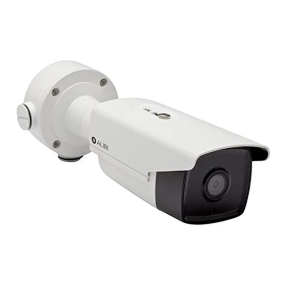
ALI-IPU3130R, ALI-IPU3230R
IP Bullet Camera
Quick Installation Guide
This document guides you through the basic steps to install and configure the ALI-IPU3130R and
ALI-IPU3230R cameras. These cameras feature:
3 MP high resolution sensor
•
IR range 100 ft (ALI-IPU3130R) and 260 ft (ALI-IPU3230R)
•
Full 1080P HD real-time video with H.264 compression
•
3D-DNR noise reduction, Wide Dynamic Range (WDR), Backlight compensation
•
Dual power capable - Power over Ethernet (PoE) or 12 Vdc
•
Weatherproof - IP66 rated
•
For more information about the software features of this camera, please refer to the ALI-IP Camera
Software User Manual.
Articulated
mounting
bracket
Camera body
ALI-IPU3130R, ALI-IPU3230R camera
Camera base
locator pins
Top (up)
Bottom (down)
Conduit port (2)
Junction box detail
Camera drop cables
1
www.observint.com
Junction box assembly
(see detail below)
Camera mounting base
Sun Shield
Mounting screw
hole (4)
Hole for camera
mounting screw (4)
Cable access
through mounting
surface
Ethernet connector -
PoE capable
12 Vdc Power
connector
What's in the box
Your camera includes the items shown below.
Adapter
plate
Surface
mount drill
template
Step 1.
Install the camera
The camera includes hardware to install it directly to the Junction box provided, to a mounting surface
(without the junction box), or to a double-gang electrical box using the adapter plate provided. When
using the junction box, camera LAN and power drop cables can attach to extension cables inside the
box. The camera with or without the junction box can be installed on a ceiling (horizontal surface) or
wall (vertical surface). To install the camera, do one of the following:
To mount the camera using the Junction box
1.
Determine the best fasteners for securing the Junction box to mounting surface. The mounting
hardware provided is suitable for most surfaces.
2.
Remove the junction box from the camera assembly by loosing the four captive screws.
3.
Attach the drill template to the surface. Mark the location of the Junction box mounting screw
Lens
holes. If routing extension cables for the LAN, power, alarm devices, etc. through the mounting
surface, mark the location for that hole too. NOTE: If installing the box onto a wall, observe
the orientation for TOP and BOTTOM orientation markings inside the box and on the camera
mounting base, and orient the drill template properly.
Mounting surface
Drill template
Junction box mounting screws (4)
4.
Drill holes in the mounting surface for the mounting screws and extension cables (if necessary).
5.
Secure the Junction box to the mounting surface using appropriate fasteners.
6.
Route the network LAN and power extension cables between the junction box and the devices
they connect to. Do not apply power to the extension cables at this time.
7.
Attach the camera safety cable to the safety hook inside the junction box.
To mount the camera onto a surface without the junction box
For this mounting option, the drop cables can be routed through the mounting surface, or through the
cable channel in the mounting base.
Security L-wrench
Weatherproof
Mounting
LAN coupling
hardware
Junction box
Safety cable
Orientation mark
Mounting base screws (4)
ALI-IPU3130R-3230R_CQ
CD-ROM with manuals
and software
Junction box
(top view)
Camera
4/23/15