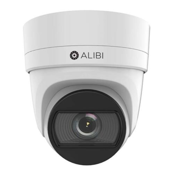
ALIBI ALI-NS2126R Manual de instalación rápida - Página 2
Navegue en línea o descargue pdf Manual de instalación rápida para Cámara digital ALIBI ALI-NS2126R. ALIBI ALI-NS2126R 7 páginas. 6mp vari-focal ip turret camera
RESET: To restore the camera to its default settings, hold down the RESET button for about 10 seconds
NOTE
when the camera is powering on or rebooting. Reset will deactivate the camera and restore the default
IP address, port number, configuration settings, etc.
6.
Insert the microSD card into the slot. The card should slide in smoothly. Push the card in until it
clicks and is held in place.
7.
Reinstall the maintenance panel cover. Ensure that the cover seal is positioned correctly before
tightening the cover screws.
Remove the adapter plate
1.
With the camera laying dome up on a clean, soft surface, use the L-wrench provided to loosen
the adapter plate screw. See the drawings in "Install microSD card" on page 1.
2.
Remove the adapter plate from the camera base assembly.
Install the adapter plate
The camera can be mounted onto a wall or ceiling, or onto a single-gang or double-gang electrical box.
If mounting the camera onto a wall or ceiling, screws and wall inserts appropriate for many surfaces
are provided. However, more appropriate fasteners may be required. The mounting surface should
support at least four (4) times the weight of the camera.
When selecting a mounting location for the camera
• Make sure that there are no reflective surfaces near to the camera lens. IR light from the camera may
NOTE
bounce back onto the lens causing reflections.
• Determine how wiring is routed into the camera. The cable can be routed through the mounting
surface and access hole in the mounting plate or through the side inlet.
To attach the adapter plate to a mounting surface:
1.
a.
Use the adapter plate as a template to mark the location of the holes for the mounting
screws. Use the four holes marked "1" for mounting screws to attach the camera to a
surface or double-gang box. Holes marked "2" are used for mounting onto a single-gang
box. The "FRONT" mark should point toward the front (lens) of the camera. If routing the
cables into the camera through the mounting surface, mark the location of the opening in
the adapter plate for the cables.
b.
Drill holes in the mounting surface where needed for the fasteners and cable routing.
c.
Attach the adapter plate to the mounting surface using four screws.
2.
To attach the adapter plate to a gang box:
The mounting surface must be able to support at least four times the weight of the gang box with the
NOTE
camera.
a.
Install the gang box in the appropriate location. The adapter plate can be secured to a
single- or double-gang box.
b.
Remove the cover screws from the gang box.
c.
Align the screw holes in the adapter plate with the cover screw holes in the gang box, and
then secure the plate to the box with the cover screws removed previously. For a double-
gang box, use the screws through holes in the plate marked "1". For a single-gang box,
use the screws through the holes in the plate marked "2".
3.
Route the interface cables through the gang box and then through the adapter plate.
Connect the interface cables
Interface cables are routed into the camera base through sealing plugs. These cables are then
terminated on a connector panel inside the base. Connectors are provided for alarm IN and OUT leads,
LAN (PoE capable) RJ-45 cable, and audio IN and OUT (3.5 mm jacks).
2
www.observint.com
An insertion tool used to puncture the sealing plugs and route the cable through is provided.
1.
Loosen the two captive bottom cover screws in the camera base to open the bottom cover, and
then attach the safety cable in the base to the hook on the adapter plate.
Safety cable
Cover
screws
Side inlet
2.
Remove the largest sealing plug from the junction box. This plug will be used for the LAN cable.
Interface
connectors)
3.
To route the LAN cable through the sealing plug:
a.
Remove the large sealing plug (marked LAN) from the base cover.
b.
Clip the insertion tool provided onto the RG-45 connector of the LAN cable. See a.
c.
Force the insertion tool with the LAN cable through the sealing plug. Observe the
orientation of the sealing plug in the drawing below. See b.
Insertion tool
Sealing plug
a.
b.
Slide the sealing plug down the cable past the RJ-45 connector. See c.
d.
e.
Remove the insertion tool from the LAN cable. See d.
f.
Reinstall the sealing plug with the LAN cable into the bottom cover, and then plug the
LAN cable into the LAN interface connector.
4.
Using the previous steps as a guide, use the insertion tool to install the power, audio and alarm
cables as needed through the sealing plugs in the base cover. Attach these cables to the interface
connectors.
5.
Reattach the bottom cover to the camera base. Ensure that seal on the bottom cover and the
sealing plugs are properly installed before tightening the cover screws.
Secure the camera to the adapter plate
1.
Holding the camera by the camera base, insert the three raised studs on the bottom cover into
the slots in the adapter plate, and then rotate the camera right to fully seat the studs in the slots.
Adapter plate
Bottom cover
Raised studs
for slots in the
adapter plate
Sealing
plug (4)
Sealing plug
for LAN (PoE)
Camera base
c.
d.
© 2019 Observint Technologies. All rights reserved.