Jandy Jandy Pro Series Manual de instalación y funcionamiento - Página 16

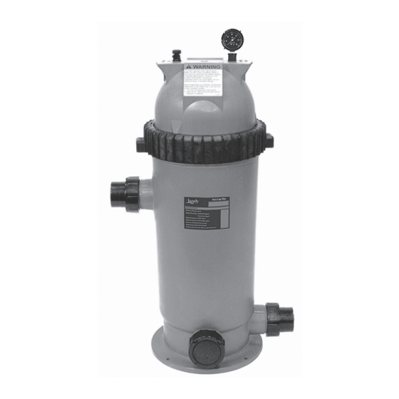
Navegue en línea o descargue pdf Manual de instalación y funcionamiento para Bomba de agua Jandy Jandy Pro Series. Jandy Jandy Pro Series 20 páginas. Single element cartridge pool & spa cs filters
También para Jandy Jandy Pro Series: Manual del usuario (12 páginas), Manual de instalación (16 páginas), Manual de instalación y funcionamiento (20 páginas), Manual del usuario (20 páginas), Manual (8 páginas), Manual de inicio rápido (2 páginas), Instrucciones de instalación (2 páginas), Manual de instalación y funcionamiento (16 páginas), Manual de instalación y funcionamiento (16 páginas), Manual de instalación y funcionamiento (16 páginas)

Jandy Jandy Pro Series Manual de instalación y funcionamiento
Page 16
ENGLISH
5.2.2 Observe Operation
1.
Restore power to the control box and observe the
operation. The control box is working if steps 2-7
in this section occur.
2.
The Power light illuminates and turns green.
3.
The Sensor light illuminates and turns yellow.
4.
The Low Water Sensor light turns yellow.
5.
Voltage is sent to the valve and relay.
a.
After 20 seconds, the Fill light turns green
and you can measure 24VAC across the blue
wires with an AC volt meter.
b.
After 20 seconds, the Low Water Cutoff light
turns green and you can measure 24VAC
across the red wires with an AC volt meter.
6.
Make sure the sensor probes are touching the
water. Then connect the three (3) sensor wires
to the sensor. Refer to Table 1, Sensor Wire
Connections, page 11.
a.
Connect the black wire for the Sensor
Common probe with the yellow wire in the
control box.
b.
Connect the white wire for the Fill Sensor
probe with the yellow/blue wire from the
control box. The Fill light will turn off after
20 seconds.
c.
Connect the red wire for the Low Water
Sensor probe to the yellow/red wire from the
control box. The Low Water Cutoff light will
turn off after 20 seconds.
7.
Use an AC volt meter to confirm that there is 0
voltage at the blue wires in the control box and 0
voltage at the red wires in the control box.
Jandy Pro Series Levolor
II Electronic Water Leveler
®
Models K-2100
5.2.3 Manual Valve Override
There is a manual ON/OFF lever on the valve body
located just below the solenoid. See Figure 6, Manual
Valve Lever, page 9.
If you are having a problem with the system and want to
override the electronic water Levolor, you can manually
open the valve by putting the lever in the up position ↑
(12 o'clock) for manual filling.
During normal operation, the lever must be in the
horizontal position → (3 o'clock) for controlled filling.
5.2.4 Troubleshooting Specific Conditions
Use the troubleshooting flow charts on the following
pages to find and fix these problems:
|
- Fill Valve Will Not Turn OFF
- Fill Valve Will Not Turn ON
Installation and Operation Manual