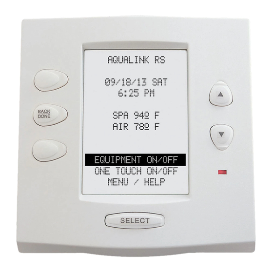
Jandy AquaLink RS series Manual de instalación - Página 10
Navegue en línea o descargue pdf Manual de instalación para Control Panel Jandy AquaLink RS series. Jandy AquaLink RS series 16 páginas. Dual equipment systems

- 1. Section 2. System Overview
- 2. Plumbing Diagrams
- 3. Connecting Power and Mounting Bezel
- 4. Connecting Control Panel Cable to Pcb
- 5. Section 3. Power Center Connection (Low Voltage)
- 6. Dip Switch Functions
- 7. Dip Switch Settings for Pool and Spa Combination
- 8. Section 5. Dual Equipment Wiring Diagram
Page 10
3.4
Connecting heater to Low Voltage
Terminal
NOTE Millivolt, electronic ignition, or heat pump with
thermostatic circuitry of 24 VAC or less.
1. If you are connecting a Low Voltage pool
heater (for example, a Jandy Brand heater),
connect two 14 gauge wires, designed
for use in hot environments, to the proper
terminals on the 10 pin terminal bar (see
Figure 4). If you are connecting a High
Voltage pool heater, contact Jandy for
instructions.
Green 10-pin Terminal Bar
4 3 2 1
4 3 2 1
S1
RESET
AUTO
SERVICE
TIME OUT
S2
Power Center PCB/Bezel
Heater Thermostat
to Max.
Factory Installed
Wire Loop
Terminal 1
Terminal 2
Figure 4.
Jandy heater Connection
2.
Bring the 2 heater wires from the PCB over
to the heater and wire nut in series with
heater circuitry as if you were wiring a
fireman's switch or a heater delay.
3.
Turn the heater thermostat to the Spa
position and maximum setting.
4.
Turn heater toggle switch on.
5.
Do not disconnect high limit or pressure
switches.
NOTE For Spa Heater, make connection to the Spa
heater Interface Board and plug it into the Spa
Heater socket.
#14 Gauge Wire
6 5 4 3 2 1
10 9 8 7 6 5 4 3 2 1
Heater Toggle
Switch to ON
Heating
Wiring
Jandy Heater Fireman's
Switch Connection
3.5
Connecting Equipment to PCB
Connect the high voltage relay plugs into their
appropriate sockets according to the wiring
diagram located on the inside of the Power Center
door (see Section 5, Figure 5).
NOTE Pool filter pump socket is on the far left of the
PCB and the spa filter pump relay socket is on
the right after aux 6 socket.
3.6
Setting DIP Switches
See the wiring diagram in Figure 5 to set all DIP
Switches for optional operation features.
3.7
Installing Power Center Faceplate
Use the screws provided to install and secure the
Power Center Faceplate onto the Power Center.
Connect the Power Center can to the main circuit
breaker and restore power to the unit and check it
for proper operation.
