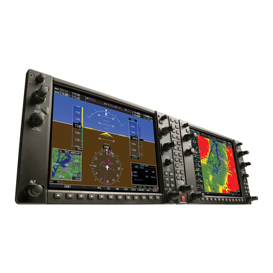
GTX 33/GTX 32
The GTX 33 Mode-S and GTX 32 Mode-C transponders provide the ground radar surveillance capability to the G1000 system.
Both transponders are solid-state units and require no warm-up time. As installed in most aircraft, these units transition to an ALT
reporting mode at a ground speed of 30 kt. This is designed to minimize pilot workload when at the threshold of the runway. Proper
operation can be verified by looking at the transponder box on the PFD and ensuring that the appropriate mode is displayed in green
and that an "R" indication appears, indicating that the system is being interrogated. Typically, only one Mode-S or Mode-C transponder
is installed per aircraft. The GTX 33 Mode-S transponder also receives and presents (if selected) airborne traffic, using the FAA-pro-
vided TIS (Traffic Information Service) system.
NOTE: For more information on TIS, refer to "http://www.tc.faa.gov/act310/projects/modes/tis.htm".
Failure Mode(s)
If the transponder fails, a red "X" appears over the transponder box of the PFD (see Figure 4) and an advisory message appears.
GEA 71
The GEA 71 Engine/Airframe Interface is the main processing unit for all engine instrumentation data, which includes manifold
pressure, RPM, oil temperature/pressure, electrical system, exhaust gas temperature (EGT), cylinder head temperature (CHT), fuel and
vacuum system—the latter depending upon the aircraft. The EIS can also contain annunciations such as those associated with doors
and canopies.
Failure Mode(s)
If the GEA 71 fails, all engine/airframe data is lost. However, a much more likely scenario would be one in which the EGT/CHT
probes would fail, or in which other engine/airframe sensors would become inoperative. Those items would display a red "X" to indi-
cate this type of failure (see Figure 4). EIS-related advisories may also appear, depending upon the aircraft.
GMA 1347
The GMA 1347 is a solid-state digital audio panel that integrates NAV/COM audio, intercom system and marker beacon. The unit
operation is conventional when compared to that of other audio panels. Pressing the COM/MIC buttons selects the COM radio to be
used for both transmitting and receiving communications. Pressing the COM button only allows the selected COM radio to be moni-
tored. Pressing a NAV button activates/deactivates the audio for the corresponding NAV radio. The intercom controls are located on
the lower portion of the audio panel; the small knob controls pilot volume and the large knob controls copilot and passenger volume.
The audio panel is auto-squelch enabled and also has clearance recorder capability. The reversionary mode (DISPLAY BACKUP)
button for the GDU 1040 displays is located on the lower portion of the GMA 1347.
Failure Mode(s)
In the event of failure, the GMA 1347 has an analog emergency mode that automatically connects the pilot to COM1. This allows
the pilot to retain communication capabilities over one COM radio, even though the audio panel/intercom system has become inopera-
tive.
190-00368-02 Rev. A
G1000 SYSTEM COMPONENTS
Garmin G1000 Guide for Designated Pilot Examiners & Certified Flight Instructors
5

