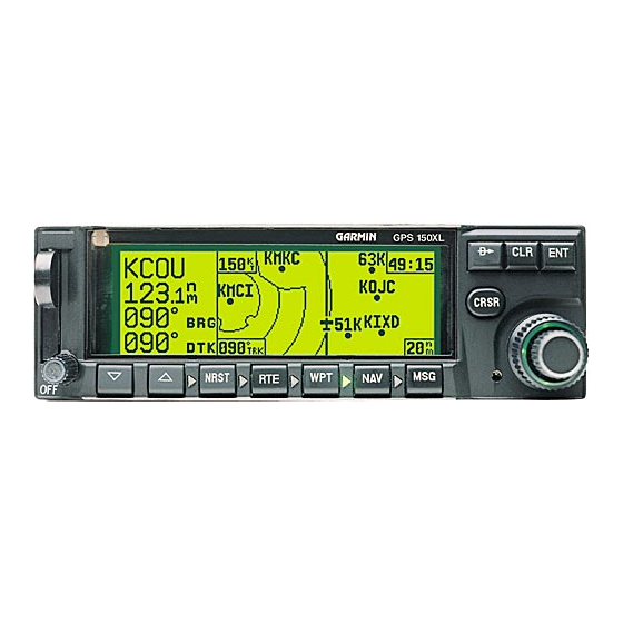
Garmin GNC 250 Manual de mantenimiento y reparación - Página 2
Navegue en línea o descargue pdf Manual de mantenimiento y reparación para Pantalla de aviónica Garmin GNC 250. Garmin GNC 250 20 páginas. Garmin gnc 250: quick reference
También para Garmin GNC 250: Manual de referencia rápida del piloto (25 páginas), Manual de instalación (44 páginas)

Paragraph
1.1 GENERAL DESCRIPTION......................................................................................................1
1.2 DETAILED DESCRIPTION....................................................................................................2
1.2.1 Control/Display Unit (CDU)........................................................................................4
1.2.2 CPU Board Assembly ....................................................................................................6
1.2.2.1 Central Processing Unit (CPU) ......................................................................6
1.2.2.2 Power Supply Circuits...................................................................................6
1.2.3 GPS Receiver..................................................................................................................6
1.2.4 Interface Board and Data Cards....................................................................................7
1.2.5 VHF Communications Transceiver ..............................................................................7
2.1 TROUBLESHOOTING EQUIPMENT REQUIRED .................................................................9
2.2 SELF-TEST FAILURES...........................................................................................................9
2.3 INITIAL TROUBLESHOOTING OPERATIONS..................................................................11
2.3.1 Power Supply Check...................................................................................................11
2.3.2 Internal Clock Check ..................................................................................................11
2.4 TROUBLESHOOTING CHART.............................................................................................14
2.5 TROUBLESHOOTING COMM SECTION............................................................................16
3.1 REMOVAL OF THE COVERS................................................................................................18
3.2 BOARD AND MODULE DISASSEMBLY.............................................................................18
3.2.1 Control/Display Unit Removal .................................................................................18
3.2.2 Altitude Decoder Board Removal ..............................................................................18
3.2.3 Interface Board Removal............................................................................................19
3.2.4 CPU Board Subassembly Removal............................................................................19
3.2.5 GPS Receiver Assembly Removal..............................................................................20
3.2.6 Power/Volume Switch Removal.................................................................................20
3.2.7 Rotary Switch Assembly Removal............................................................................21
3.2.8 Display Board Removal .............................................................................................21
3.2.9 Remote Battery Pack ..................................................................................................21
3.3 REASSEMBLING THE UNIT ...............................................................................................21
TABLE OF CONTENTS
SECTION 1
INTRODUCTION
SECTION 2
SECTION 3
DISASSEMBLY INSTRUCTIONS
i
Page
