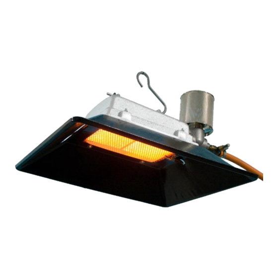
Alke 61 Series Manual de uso e instalación - Página 6
Navegue en línea o descargue pdf Manual de uso e instalación para Calentador Alke 61 Series. Alke 61 Series 8 páginas. Atmospheric ceramic luminous infra-red heaters for use in well ventilated areas
También para Alke 61 Series: Manual de uso, mantenimiento e instalación (13 páginas)

Fault finding table
Trouble
Burner does not light.
Burner extinguishes
after lighting
Flames leave the
- confines of the burner,
- or are sooting,
- or a blue cloud is
under the reflector
The burner is only partly
glowing
Burner makes a lot of
roaring noise (back
flash)
The burner do not work
at minimum position
Heater will not attain the
desired temperature
Declaration of conformity
We, Alke B.V., located in Scherpenzeel, The Netherlands, hereby declare that the 21, 41, 61 and 81 series,
marked on their data plates with CE and with the CE approval/production supervision number 0063 of Kiwa
Gastec are in compliance with the Directive on appliances burning gaseous fuels (2009/142/EC) (ex
90/396/EEC)
Scherpenzeel, 01-01-2011
Adri van Alphen
Managing Director
Version: jan 2011
Action
Check if the gas valve of the gas cylinder or gas line is open
Check if the gas cylinder is empty
Note that first ignition will take 60 or more seconds before gas is available
Check if the gas injector (12) is blocked
Check if the gas pressure / gas quality is identical to the data plate information
Keep button safety device (15) pressed for a longer period (up to 25 seconds)
Check if the thermocouple (19) is connected properly to the gas safety device
Check if the thermocouple tip (19) senses the heat of the burner
Thermocouple (19) or magnetic coil of the safety device (15) is broken
Gas pressure lower than minimum requested
Gas heater not suspended at 15 degrees angle
Gas pressure is too high. Check the gas pressure with the data plate
Check if the gas pressure regulator is broken
Wrong gas is used. Check data plate for the correct gas supply
Venturi/air inlet is blocked/dirty
Check the size of the venture (8) and injector (12) with the table
Air filter (11) is dirty or not enough fresh air available
Check position axle bore (14) and move to correct position
Gas heater not suspended at 15 degrees angle
Wrong gas or pressure is used. Check data plate with the gas supply
Check if the injector (12) or venturi (8) are blocked or dirty
Check the injector (12) and venture size (8) with the table
Check the setting of the thermostat (24)
Check if pipe sizes or gas hoses have sufficient capacity
Check if ceramic stone (22) is broken
Check gas quality, and if gas pressure is to high, with data plate information
Check position axle bore (14)
Check size venturi (8) (Note that some types no separate venturi is needed:
size is 15mm)
Gas pressure is not correct. Check the gas pressure with the data plate
Wrong gas is used. Check data plate for the correct gas supply
Check the size of the venture (8) and injector (12) with the table
Injector (12) (partly) blocked
Check if the thermocouple tip (19) senses the heat
Sensor or wire thermostat TH (24) is broken
Thermostat TH valve adjusting mechanism (24) is blocked
By-pass hole thermostat (24) is blocked
There is insufficient heat in the building for heat loss (i.e., not enough heaters).
The thermostat TH sensing bulb (24) is incorrectly placed
The thermostat TH (24) is out of calibration or broken
Injector (12) partly blocked
Derk Jan Keurhorst
Managing Director
6
Manual number: 0009 0520EN
