Garmin TR-1 Gold Manual del usuario - Página 7
Navegue en línea o descargue pdf Manual del usuario para Sistema GPS marino Garmin TR-1 Gold. Garmin TR-1 Gold 38 páginas. Throttle actuator
También para Garmin TR-1 Gold: Manual de funcionamiento básico (9 páginas), Referencia rápida (2 páginas), Instrucciones de montaje (7 páginas), Instrucciones de instalación (4 páginas), Referencia rápida del mando a distancia del propietario (2 páginas)

Access
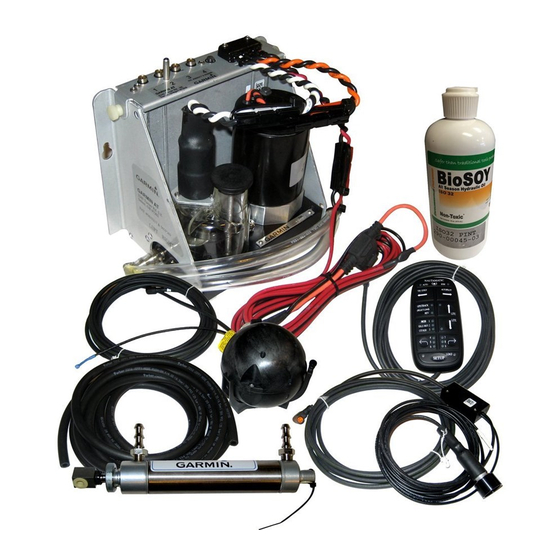
The Electrohydraulic Unit is the place where all the components connect together and the place where
fluid is added and fluid level is checked. Leave room for service loops in the cables and hoses.
The Deckmount switch should be easy to reach with your free hand when your other hand is on the
kicker tiller. This can be done after the initial turn on blinking setup is complete. In case of an
emergency, quick access to the deckmount switch is a good idea, by pressing the button once it will
take the autopilot to standby, allowing you to take control of the tiller handle. Pressing the button
again will return it to autopilot mode.
If you intend to hook up to GPS, the connection between the GPS and the autopilot is made at the
Sensor ball and the NMEA 0183 output on your GPS.
Protection
Locate the Electrohydraulic unit and Sensor ball in places where they will not get submerged or
exposed to wash down.
Use a quality electrical insuating grease compound on all electrical connections (Dow Corning
#4) except the orange connectors # 1,2,3, & 4.
Moving Parts
Hoses and cables that connect the Electrohydraulic unit to the engine mounted components
need to be free from binding and kinking. Be sure to remember your kicker moves up and down
on the lift bracket, tilts up and down, and steers lock to lock.
Hose Length
Try to keep the hose length between the steering cylinder and the Electrohydraulic unit short. But
leave enough length for movement of Kicker (See note above on moving Parts).
Magnetic Environment
The Sensor ball has a compass in it. Do not mount the ball near magnetic materials, magnets
(speakers and electric motors), or high current carrying wires. Small, vehicle fixed, magnetic
disturbances can be calibrated out, but moveable or changing magnetic disturbances such as anchors,
anchor chain, and wiper motors should be kept at least 24" away. A common problem is to have
mounted the ball near a glove box, and then someone puts tools in the glove box. Keep the Sensor
ball away from Air Ride seats.
Strain Relief and Cable Protection
Do not let the connectors on the Electrohydraulic unit be the sole support for the cables connected to
them. Use the tie wraps to tie the cables down to the Electrohydraulic frame. There are several holes
in the sheet metal frame provided for this purpose.
Don't run cables and hoses over sharp edges. Use grommets in through holes to protect the cables.
7
7
