MOONEY
M20R
electrical systems, but load shedding may be required to avoid deple-
tion of the main battery. The Emergency Bus specifically powers the
standby attitude indicator, and lighting for the standby instrumentation.
Activating the EMER BUS switch bypasses the master switch and elec-
trically feeds the standby attitude indicator and all standby lighting using
both main batteries.
The circuit breaker panel is located on the right side of the instrument
panel. Each breaker is clearly marked to show which circuit it protects.
Also, circuit provisions are made to handle the addition of communica-
tions and navigation equipment.
Standard electrical accessories include the starter, the electric fuel
pump, and the stall warning horn. Electrical accessories include the
navigation lights, anti--collision strobe lights, instrument panel lighting,
and cabin courtesy lights. Make sure the lighting and Emergency Bus
switch are off when leaving the aircraft. Leaving the lights on for an ex-
tended period of time could cause depletion of the battery.
Two lights, mounted in the overhead panel, provide instrument and
cockpit lighting for night flying. A wing tip recognition/landing light sys-
tem consists of 2 lights (one in each wing tip) and is operated by a rocker
type switch mounted in the overhead switch panel. Landing and taxi
lights are mounted on the wing leading edges on both wings.
The M20R electrical system is divided into two power buses. A simpli-
fied schematic of the electrical system is shown in the diagram which
follows.
ESSENTIAL BUS
The Essential bus is tied directly to the main aircraft battery via the non--
essential bus. When the master switch is turned on, power is immedi-
ately supplied to the Essential and non--Essential busses. The Essen-
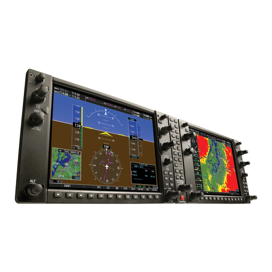
tial bus provides power to the G1000 equipment and to the backup
instruments. When the Emergency Bus switch is activated by the pilot,
the standby alternator is brought online and two relays close to power
the essential bus via a secondary path. The selected main battery (two
main batteries are available) remains online.
NON - ESSENTIAL BUS
The non--essential bus powers the autopilot, turn coordinator required
for the autopilot, the Stormscope, and GIA #2. This bus is load shed
manually by the pilot by pulling the BAT circuit breaker when the stand-
by alternator and emergency bus switch are activated.
EQUIPMENT LOCATION
The G1000 ADC and GEA LRU's are located behind the PFD and MFD,
which may be removed using a hexagonal tool. The magnetometer is
located in the right wing outboard of the landing light. The AHRS, and
remaining LRU's are located behind the cabin near the main batteries.
ISSUED 11 - 2004
REVISION A 06--2005
REVISION B 03--2006
GARMIN G1000 INTEGRATED AVIONICS SYSTEM
AFM SUPPLEMENT
31 of 33
FAA APPROVED