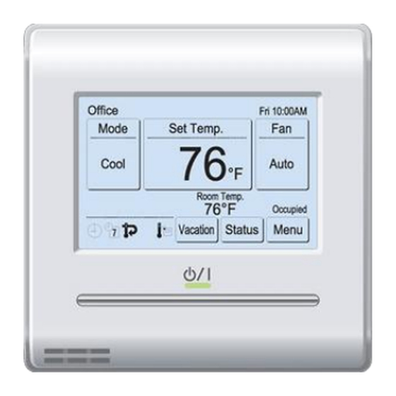
Fujitsu UTY-RNRUZ2 Manual de instalación - Página 5
Navegue en línea o descargue pdf Manual de instalación para Aire acondicionado Fujitsu UTY-RNRUZ2. Fujitsu UTY-RNRUZ2 11 páginas. Remote controller (wired type)
También para Fujitsu UTY-RNRUZ2: Manual de instrucciones (26 páginas)

Set to "2WIRE" the
DIP switch (SW1)
Remote controller
cable (Non-polar)
Connecting cable
* Layout of Connector and PC
board is varies, depending
on the type of indoor unit.
5.4.2. When connecting to exclusive terminal block
(1) Connect the end of remote controller cable directly to the exclusive
terminal block. Set to "2WIRE" the DIP switch (SW1) on the PCB
(printed circuit board) of the indoor unit.
Terminal block
Remote controller
cable (Non-polar)
* Layout of terminal block and
PC board is varies, depend-
ing on the type of indoor unit.
Tightening torque
M3 screw
(Remote controller / Y1, Y2)
For "Group control" or "Multiple remote control", refer to the following
figure on how to connect to the indoor unit terminal.
GOOD
Diameter of cables
are different
6. SETTING THE REMOTE CONTROLLER
6.1. Initialization procedure
After remote controller installation work is complete, perform initialization
using the following procedures before starting to use the system.
(*: Items that indoor unit does not support are not displayed.)
Turn on the
6.2.1. Turn on the power . ..................................... 5
power
6.2.2. Language Setting . ...................................... 5
6.2.3. R.C. Master/Slave Setting ......................... 5
Setting of first
6.2.4. Date and Time Setting ............................... 5
time start
6.2.5. Temp. Unit Setting...................................... 6
6.2.6. Password Default Setting .......................... 6
6.3.4. R.C. Group Name Setting . ......................... 7
6.3.5. RC Sensor Setting* . ................................... 7
6.3.6. Master Indoor Unit Setting ......................... 7
6.3.7. Password Setting (administrator password) ..7
Initial setting
6.3.8. Display Item Setting ................................... 7
6.3.10. Deadband Setting ...................................... 8
6.3.11. Optimum Start Setting................................ 8
6.3.12. I.U. Display Number Setting* ..................... 8
Initialization end
Indoor unit
PC board
Connector CNC01
(onboard)
SW1
Connector
(adapter)
Indoor unit
PC board
Indoor unit
PC board
Set to "2WIRE" the
DIP switch (SW1)
4.4 to 5.3 lbf·in
(0.5 to 0.6 N·m)
PROHIBITED
Connect the cables
to 1 side
6.4.1. Error History . .............................................. 8
6.4.2. Setting Status List ...................................... 8
6.4.3. Filter Sign Reset* ....................................... 8
6.4.4. Version ....................................................... 9
6.4.5. Test Run . .................................................... 9
Other Settings
6.4.6. R.C. Address Setting.................................. 9
6.4.7. I.U. Address Verification . ............................ 9
6.4.8. Function Setting ......................................... 9
6.4.9. Installer Password Change . ..................... 10
6.4.10. Initialization .............................................. 10
After installing this unit, perform the test run to confirm that the unit is
operating properly. Then, explain the operation of this unit to the cus-
tomer.
6.2. Setting of first time start
6.2.1. Turn on the power
CAUTION
Recheck the wiring. Incorrect wiring will cause trouble.
When initially starting up this unit, the following setting screen will be
displayed. Settings configured at this stage can be changed afterwards.
If an error screen is displayed, shut down all
unit power, and check the connections. After
resolving the problem, turn on the power
again.
If "Please set the address correctly." is
displayed, touch [Close], and the "RC Ad-
dress Setting" screen (refer to 6.4.6) will be
displayed. After setting, please restart this
unit.
6.2.2. Language Setting
1.
The "Language Setting" screen has two pages. You can switch be-
tween the pages by touching [Next Page] or [Previous Page]. Touch
the language to be used.
Touch [OK] to
Language Setting
display the "R.C.
English
Master/ Slave
Deutsch
Setting" screen.
Cancel
6.2.3. R.C. Master/Slave Setting
1.
(a) If the remote controller is a single
connection, this setting is omitted. Pro-
ceed to "6.2.4. Data and Time Setting".
(b) If a remote controller has multiple con-
nections, and if "Master" is initially set,
all other units will be set to "Slave".
Please set only one Master remote controller. Units other than Mas-
ter are set to Slave automatically.
When remote controllers are set to "Slave", setting items will be
restricted.
Touch [OK] to display the "Date and Time Setting" screen.
6.2.4. Date and Time Setting
1.
Touch the [Date] on the "Date and Time Setting" screen. The "Date"
screen is displayed.
2.
Touch [ ] or [ ] to set the year, month, and date. Touch [OK] to
return to the "Date and Time Setting" screen.
3.
Touch the [Time] on the "Date and Time Setting" screen. The "Time"
screen is displayed.
1.
2.
Date and Time Setting
Sun 12:00AM
Date
Date
Time
Day
01/ 01/2017
12:00 AM
Date Format
Day/Month/Year
01
Time Format
12:00-11:59AM/PM
Summer Time Setting
Disable
Cancel
OK
Cancel
Error
Code 01
Error (code:XX.X)
Please set the address correctly.
Close
Language Setting
Page 1/ 2
Français
Р
Italiano
Ελληνικά
Język
Español
Português
Türkçe
polski
Next
Previous
OK
Cancel
Page
Page
R.C. Master / Slave Setting
Master
Slave
Cancel
OK
3.
Date and Time Setting
Sun 12:00AM
Date
Time
Month
Year
01/ 01/2017
12:00 AM
01
2017
Date Format
Day/Month/Year
Time Format
12:00-11:59AM/PM
Summer Time Setting
Disable
Cancel
OK
OK
Page 2/ 2
Dutch
OK
Sun 12:00AM
En-5
