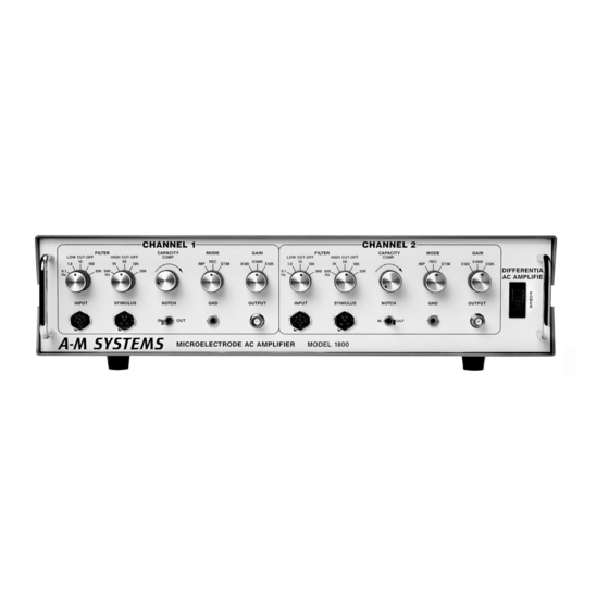
A-M Systems 1800 Manual - Página 9
Navegue en línea o descargue pdf Manual para Amplificador A-M Systems 1800. A-M Systems 1800 14 páginas. Microelectrode ac amplifier

Overview
The Head Stage Probe, containing a high input impedance, low-noise, differential
amplifier, is connected to the Model 1800 through a 9-pin Input connector assigned to
each channel. The Mode Switch for each channel controls the input configuration of
the Probe attached to that channel as well as the operation of the subsequent stages of
the amplifier. In Record Mode, a combination of the Probe and the main circuit amplify
the signal which appears across the two electrodes attached to the Probe. In Stimulus
Mode, the signal at the Stimulus connector to be applied to the electrodes and the
Probe monitors the stimulus current by measuring the voltage developed across a 1 kΩ
resistor in series with the electrode. In Impedance Mode, an internally calibrated
current is passed through the Probe to one electrode, and the Probe monitors
electrode impedance by measuring the voltage that develops across the two
electrodes.
The signal from the Probe passes through the differential amplifier which has a unity
gain in Record and Stimulus Modes and a gain of x0.01 in Impedance Mode. The
signal then passes through the Low Cut-Off Filter and is increased by a factor of 10.
Next the signal enters the Notch Filter if it is activated. Finally the signal passes
through the High Cut-Off Filter which has a unity gain in Stimulus and Impedance
Modes and an adjustable gain controlled by the Gain Switch while in Record Mode
A-M Systems
131 Business Park Loop, P.O. Box 850 Carlsborg, Wa 98324
Telophone: 800-426-1306 * 360-683-8300 * FAX: 360-683-3525
E-mail: [email protected] * Website: http://www.a-msystems.com
Theory of Operation
Figure 2. Main circuit description and block diagram
*Only for impedance mode
**Only for record mode
5
