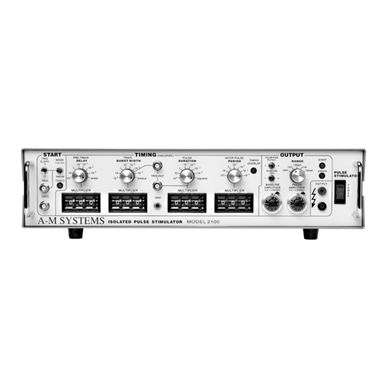
A-M Systems 2100 Manual de instrucciones - Página 12
Navegue en línea o descargue pdf Manual de instrucciones para Instrumentos de medida A-M Systems 2100. A-M Systems 2100 19 páginas. Isolated pulse stimulator

The operation of the Model 2100 is summarized in the block diagram (see the figure on
Page 11). Not shown are all of the interconnections with the microcontroller. The
internal microcontroller plays an important role in setting the signal path, but does not
directly contribute to the dynamic characteristics. It scans the front panel switches,
and sets the control values for the logic arrays. It programs the internal counters,
which along with the other hardware achieve the necessary sub-microsecond speeds.
Pulse generation starts either from an input trigger signal (from Trig In), or an internally
signal (Free Run mode). A Delay timer counts the 10MHz clock until its count value is
exhausted. At this point, the Burst, Period, and Duration timers are started. If the
Burst timer has not expired by the end of the Period, the Period and Duration timers
are restarted. If the Biphasic mode has been set, the Duration timer is restarted at the
end of the initial Duration, and the sign of the output pulse is reversed, doubling the
total duration.
The system state (pulse on, pulse sign, baseline sign [+/0/-]) is transmitted to the
isolated section via optoisolator. The baseline and pulse amplitudes are selected by
an analog switch. The resulting signal is amplified by a variable-power-supply discrete
operational amplifier. The amplifier connections and gain is modified to provide two
voltage and three current ranges.
Timing overlap errors are detected by a logical decision computation rather than by
testing for counter collisions. This provides instant feedback, rather than waiting up to
an hour for such a collision to occur. Output errors are measured by sensing the
output amplifier's differential input voltage. Under normal conditions, this is a negligible
voltage. If the amplifier fails to deliver the requested signal the window comparator
testing this voltage sends this message (via optoisolator) to the logic section, turning
on a warning LED.
A-M Systems
Theory of Operation
131 Business Park Loop, P.O. Box 850 Carlsborg, WA 98324
Telephone: 800-426-1306 * 360-683-8300 * FAX: 360-683-3525
E-mail: [email protected] * Website:
http://www.a-msystems.com
9
