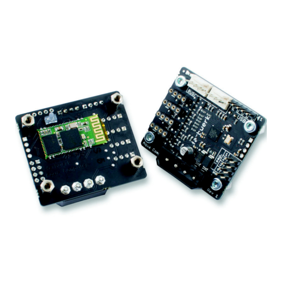
Aqua Computer farbwerk Manual de uso e instalación - Página 5
Navegue en línea o descargue pdf Manual de uso e instalación para Controlador Aqua Computer farbwerk. Aqua Computer farbwerk 20 páginas. High power led controller for pcs

aqua
computer
5. 5. 5. 5. Electrical connections
Electrical connections
Electrical connections
Electrical connections
5.1. Connector overview
5.1. Connector overview
5.1. Connector overview
5.1. Connector overview
ATTENTION: Completely turn off your power supply or disconnect the mains pow-
er cord from the wall outlet before connecting or disconnecting any cables to/from
the device!
Please refer to the following chapters for details on the individual connectors.
5.2. Power supply
5.2. Power supply
5.2. Power supply
5.2. Power supply
Connect a power plug of your PC's power supply unit to this connector. Do not
use excessive force but double check the polarity of the plug if you are having
trouble to connect.
Pin assignment:
Pin 1: +12 V
Pin 2: GND
Pin 3: GND
Pin 4: +5 V
5.3. LED output 1-4
5.3. LED output 1-4
5.3. LED output 1-4
5.3. LED output 1-4
Connect up to four RGB LED strips to these outputs. Maximum current rating for
each separate color is 2.5 A at 12 V (corresponding to 30 Watts) and a total max-
imum combined current of 8 A at 12 V for all twelve color channels (correspond-
ing to 96 Watts total).
The LED output are not short-circuit proof!
Pin assignment:
Pin 1: +12 V
Pin 2: GND blue
Pin 3: GND red
Pin 3: GND green
5.4. USB
5.4. USB
5.4. USB
5.4. USB
This connector is used for USB communication to the PC and for power supply.
Connect to an internal USB header of your motherboard. Take special care to
make sure the pin alignment matches your motherboard!
© 2014-2016
Aqua Computer GmbH & Co. KG
Gelliehäuser Str. 1, 37130 Gleichen
FARBWERK
- 5 -
