Aqua Computer 34097 Manual de inicio rápido - Página 4
Navegue en línea o descargue pdf Manual de inicio rápido para Hardware informático Aqua Computer 34097. Aqua Computer 34097 8 páginas.

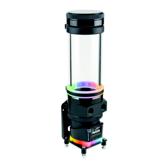
ULTITUBE D5
3.3. RGBpx LED ring
3.3.
3.3.
3.3.
RGBpx LED ring
RGBpx LED ring
RGBpx LED ring
For effective illumination of the reservoir, a RGBpx LED ring is available (product
code 34115, included in ULTITUBE D5 PRO only).
The LED ring consists of a transparent silicone ring and a black rubber LED holder.
For installation, slide the silicone ring over the top of the reservoir to your pre-
ferred position on the glass tube. Insert the rubber LED holder into the silicone
ring.
Connect the LED ring (connector marked with the word "IN") to a compatible
RGBpx output of an Aqua Computer device. A suitable cable is included in deliv-
ery. If required, additional RGBpx components can be connected (daisy chained)
to the adjacent connector (connector marked with the word "OUT").
3.4.
3.4.
3.4.
3.4. Disassembly and reassembly of the reservoir lid for filling
Disassembly and reassembly of the reservoir lid for filling
Disassembly and reassembly of the reservoir lid for filling
Disassembly and reassembly of the reservoir lid for filling
To remove the lid, hold the glass tube and turn the lid counter-clockwise. Take
care not to lose the gasket. For reassembly, place the gasket onto the glass tube
and screw the lid onto the reservoir. Do not use any tools and use only moderate
force.
3.5.
3.5. Integration into the cooling loop
Integration into the cooling loop
3.5.
3.5.
Integration into the cooling loop
Integration into the cooling loop
Connect the return line to the reservoir connector engraved with the word "IN"
and connect the other line to the remaining connector. Use light force only when
screwing in fittings in order not to damage the threads in the plastic base part!
4. 4. 4. 4. D5 NEXT
D5 NEXT
D5 NEXT
D5 NEXT
This chapter applies to variants with D5 NEXT pump only (product numbers 34100,
34109, 34110).
4.1. Detachable control unit, mounting options
4.1.
Detachable control unit, mounting options
4.1.
4.1.
Detachable control unit, mounting options
Detachable control unit, mounting options
The controller unit of the pump can be removed by pulling it off the pump motor
unit in a straight line. Make sure that no power is supplied to the pump whenever
the controller unit is being removed from or re-attached to the pump motor unit!
The controller unit can only be attached to the pump motor unit in a given orienta-
tion. Do not use excessive force but re-check the orientation if you encounter
problems re-attaching the controller unit.
The orientation of the display can only be adjusted by rotating the entire pump. In
order to rotate the pump, the mounting ring attaching the pump to the reservoir
needs to be unscrewed, which can result in coolant leakage! Completely drain the
coolant before loosening the mounting ring and remove the controller unit from
the pump! After rotating the pump, re-fasten the mounting ring by hand.
- 4 -
Aqua Computer GmbH & Co. KG
Gelliehäuser Str. 1, 37130 Gleichen
aqua
computer
© 2020
