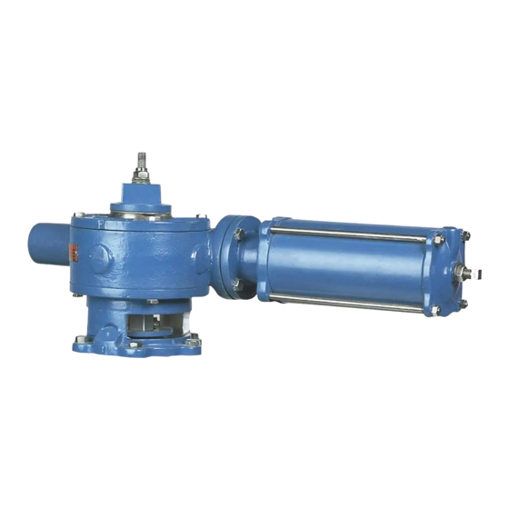
Reassembling Actuator
1. Scrape old gasket material from the actuator housing and the adapter, install a new gasket, and
then fasten the adapter to the actuator housing with the screws.
2. Line up the scribe marks on the valve and adapter made during actuator removal, then set the
adapter and housing on the valve.
3. Fasten the adapter to the valve.
4. Insert the rack bearing on the pin in the actuator housing (if replacing worn bearing).
5. Apply a liberal amount of lubricant to the rack teeth and the back of the rack, which will contact
the rack bearing, and then install the rack in the housing.
6. Apply a liberal amount of lubricant to the gear sector teeth and journals, then place the gear
sector in the housing and carefully align the teeth with the rack as marked during disassembly.
NOTE:
It may be necessary to loosen the adapter mounting screws and move the housing a small
amount to align the gears. Be sure to retighten the mounting screws after aligning the gears.
7. Scrape the old gasket material from the actuator housing and cylinder head, and then place a
new gasket on the cylinder head.
8. Install the cylinder/rack rod assembly by sliding the rack rod through the rack then fasten the
cylinder to the housing.
If the rack rod is not attached to the cylinder, clean the threads of both the rack rod and
NOTE:
the cylinder shaft, then apply Loctite to the cylinder shaft threads and screw the rack rod onto
the cylinder shaft.
9. Slide the spacer, spring washers and nuts onto the rack rod. See Figure 4 for spring washer
arrangement.
10. Screw one nut onto the rack rod until the spring washers are completely compressed, and then
loosen the nut just until the washers return to normal shape.
11. Screw the other nut onto the rack rod and tighten the two nuts against each other.
12. Set a new cover gasket on the housing, then install and fasten the top cover on the housing;
make sure the scribe marks line up.
13. Slide the bearing washer down the plug stud.
14. Screw the plug adjusting nut down the plug stud until it touches the bearing washer.
15. Turn the plug adjusting nut clockwise until there is .010" clearance between the plug face and
the body seat. (If the valve is used with paper stock, the clearance should be .030".
Note:
The holes in the bearing washer must line up with the tapped holes in the top of the gear
sector.
16. Slide the pointer down the plug stud so that it rests on top of the bearing washer; the pointer
should point to the correct valve position. Fasten the pointer to the gear sector with the two
shorter socket head screws.
17. Slide the wrenching square down the plug stud so that it rests on top of the pointer. Fasten the
wrenching square to the gear sector with the four remaining socket head screws.
18. Screw the lock nut down the stud until it contacts the wrenching square and tighten to lock the
assembly into place.
July 2016
Cylinder Operated G-Series Actuator
(Continued)
Page 11
DeZURIK
D10191

