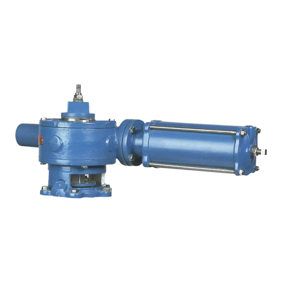
Position Stops
Valves equipped with cylinder operated G-Series actuators have stops to limit valve travel in both the
clockwise and counterclockwise directions. See the STOP ADJUSTMENTS section of this instruction
for details on adjusting the stops.
The position stops are factory set and do not require adjustment unless the actuator has been
disassembled or actuator orientation has been changed.
Stop Adjustments
Clockwise rotation of the disc is stopped when the piston rod contacts the set screw in the cylinder cap.
Counterclockwise rotation of the disc is stopped when the end of the rack rod contacts the set screw in
the end of the extension cap.
To adjust the stops, follow these steps:
1. Actuate the valve to determine the need for stop adjustment.
Accidental operation of power actuator can cause personal injury or equipment damage.
Disconnect and lock out power to actuator before servicing.
2. If adjustment is required, loosen the lock nut on the stop to be adjusted and turn the stop in or
out as required. Tighten the lock nut.
3. Actuate the valve to check the stop adjustment and repeat Steps 2 and 3 until the desired stop
setting is achieved.
Closed Stop Adjustment
1. Open the valve.
2. Loosen the jam nut on the closed stop adjusting screw, then back the adjusting screw out about
1-1/2 inches.
3. Apply air pressure to the cylinder port closest to the actuator housing until the valve is in the
closed position. The correct closed position for your type of valve is described in the Valve
Instruction.
4. After the valve is in the closed position, turn the stop adjusting screw in just until resistance is
felt as it contacts the piston in the cylinder.
5. Make sure the thread seal is intact, and then lock the adjusting screw in this position by
tightening the jam nut against the actuator.
October 2012
Cylinder Operated G-Series Actuator
Figure 2 – Position Stops
Page 5
DeZURIK
D10082

