DFRobot DFR0004 Manual - Página 8
Navegue en línea o descargue pdf Manual para Controlador DFRobot DFR0004. DFRobot DFR0004 13 páginas. Dfrduino romeo-all in one controller
También para DFRobot DFR0004: Manual (11 páginas), Manual (16 páginas)

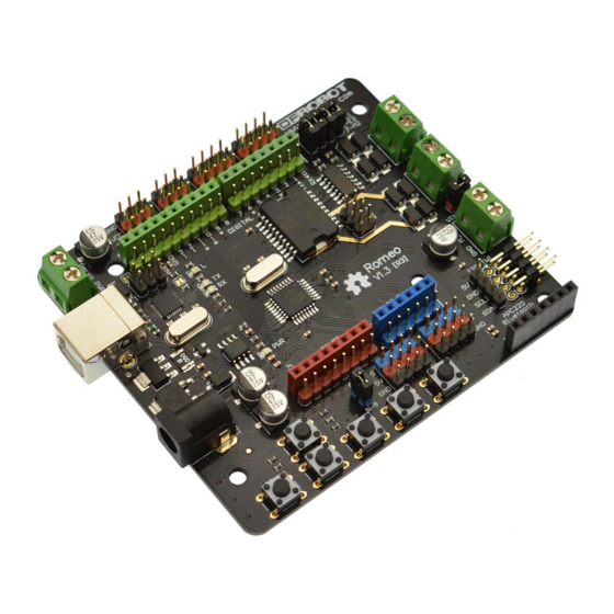
The PWM DC motor control is implemented by manipulating two digital IO pins and two PWM pins.
As illustrated in the diagram above (Figure 5), Pin 4,7 (7,8 for old Romeo version) are motor
direction control pins, Pin 5,6 (6,9 for old Romeo version) are motor speed control pins.
For previous Romeo board, the pins used to control the motor is Pin 7,8 (Direction), Pin 6,9 (Speed).
You can find the information at the right side of the Motor Control Pin Jumpers.
Sample Code:
//Standard PWM DC control
int E1 = 5;
//M1 Speed Control
int E2 = 6;
//M2 Speed Control
int M1 = 4;
//M1 Direction Control
int M2 = 7;
//M1 Direction Control
///For previous Romeo, please use these pins.
//int E1 = 6;
//int E2 = 9;
//int M1 = 7;
//int M2 = 8;
void stop(void)
{
digitalWrite(E1,LOW);
digitalWrite(E2,LOW);
}
void advance(char a,char b)
{
analogWrite (E1,a);
digitalWrite(M1,HIGH);
analogWrite (E2,b);
digitalWrite(M2,HIGH);
}
void back_off (char a,char b)
//M1 Speed Control
//M2 Speed Control
//M1 Direction Control
//M1 Direction Control
//PWM Speed Control
//Stop
//Move forward
//Move backward
