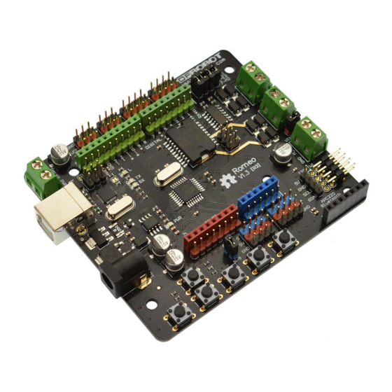
DFRobot DFR0004 Manual - Página 3
Navegue en línea o descargue pdf Manual para Controlador DFRobot DFR0004. DFRobot DFR0004 11 páginas. Dfrduino romeo-all in one controller
También para DFRobot DFR0004: Manual (13 páginas), Manual (16 páginas)

Applying Power
This is one of the most important steps in getting the Romeo up and communicating with your
host controller. You MUST make sure that you apply power to the Power Terminal using the
correct polarity. Reverse Polarity will damage the Romeo. We are not responsible for such
damage, nor do we warranty against such damage. Make sure you take time to apply power
correctly. Otherwise, it could get costly for you!
Power from USB: Simply plug USB cable, and the Romeo is able to work. Please notice that
the USB can only supply 500 mA current. It should be able to meet the most requirements for
LED lit application. However it is not enough to power DC motors or servo.
Power from Motor Power Input: Simply connect the ground wire from your supply to the
screw terminal labeled "GND", and then connect the positive wire from your supply to the screw
terminal labeled "VIN".
NOTE: Maximum supply voltage cannot exceed 14V DC.
Software
RoMeo can be programmed by Arduino IDE 0022 and above. It can be downloaded at
Arduino.cc (http://arduino.cc/en/Main/Software), Please select "Arduino UNO" as the hardware.
Romeo Configuration
Servo Power Select Jumper
As most servos draw more current than the USB power source can supply. A separate servo
power terminal is provided to power the servo individually. This option can be Enabled/Disabled
by the Servo Power Select Jumper.
When the Servo Power Select Jumper is applied, the servo is powered by internal 5V.
When the Servo Power Select Jumper is not applied, the servo is powered by external power
source.
The Romeo V1.0 uses an automatic switcher for the power source selection. When the external
power source has been applied, the servo will be automatically powered by the external power
instead of USB power.
Motor Control Pin Jumper
Applying the Motor Control Pin Jumpers will allocate Pin 5,6,7,8 for motor control.
Removing the jumpers will release the above Pins, and the motor controller will be disabled.
Tutorial
Button Press
RoMeo has 5 build in buttons S1S5 (Figure 2). S1S5 use analog input 7,
"Button Pin Map"
Pin
Function
Analog Pin 7
Button S1S5
