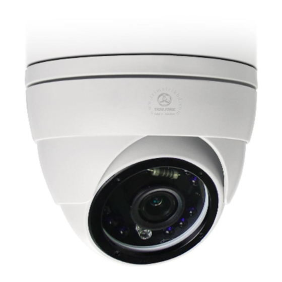
Avtech AVM2200T Manual de instalación
Navegue en línea o descargue pdf Manual de instalación para Cámara de seguridad Avtech AVM2200T. Avtech AVM2200T 4 páginas.

CAMERA INSTALLATION
TYPE1
Standard package
Installation
Guide
Camera case
Instructions
Camera
CD manual
Optional accessories
and
3-pin terminal
Wrench
block
a
TYPE2
Standard package
Installation
Guide
Camera
Instructions
CD manual
a
Step1: Disassemble the camera case into three parts as illustrated in Figure 1.
Step2: Locate where you want to install this camera (wall or ceiling), and drill holes on the wall or ceiling for securing the bracket and
routing the cables (if necessary).
Step3: Attach the bracket to the wall (or ceiling), and make sure the cables are routed and arranged properly in the bracket, as shown in Figure 2.
Step4: Secure the bracket to the wall (or ceiling), as shown in Figure 3.
Screws &
wall plugs
Step5: Slightly adjust the camera lens to where it's supposed to face, and replace Part 1 and Part 2 back, as shown in Figure 4 and Figure 5.
Step6: Hold the camera lens and Part 1, and rotate only Part 2 clockwise, as shown in Figure 5.
Step7: Power on your camera, and check the viewing angle on the PC.
(For selected model only) For focal length and focus adjustment, please check Figure 6 to know where to do.
Waterproof kit
a
Step1: Separate the dome cover from the camera.
Step2: Make sure the screw holes on the plate are aligned with the holes on the
camera base. If not, slightly loosen the two screws on the plate and rotate it.
Note: A file for its installation sticker could be downloaded from
www.surveillance-download.com/user/a_installation_sticker.pdf.
Step3: Mark the locations of the two screw holes on the ceiling or wall, and drill a hole
for each on the ceiling or wall. The distance between your camera and the
location you want to monitor should be 3 ~ 4 meters.
Step4: Fix the camera to the ceiling or wall with the supplied screws.
Step5: Connect your camera to power.
Step6: Pan, tilt and rotate the lens itself to adjust the position and viewing angle of the
camera, and fasten the two screws on the plate to fix.
Screws &
wall plugs
Step7: Replace the dome cover back to the camera.
Note: Please wipe the inner part of the dome cover against the lens for clear images.
To check the complete user manual and free PC CMS software (CMS Lite),
please scan the QR code or go to
Base
Part 1
Part 2
Figure 1
Figure 4
www.surveillance-download.com/user/m3636.swf
Figure 2
Figure 3
Figure 5
771z
Figure 6
