Allied Telesis AT-x230-10GP Manual de instalación - Página 12
Navegue en línea o descargue pdf Manual de instalación para Hardware de red Allied Telesis AT-x230-10GP. Allied Telesis AT-x230-10GP 14 páginas. Rack mount installation guide

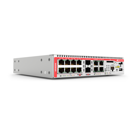
AT-x230-10GP, AT-AR3050S and AT-AR4050S Rack Mount Installation Guide
12
6. Aligning the devices
You can secure the devices into the tray with the truss head screws
through the holes on the slide-rail weld. You can use two truss head
screws per device. You can align up to two devices side by side in the
tray.
To align the faceplate of the device with the edge of the tray, attach
two truss head screws to one side of the device from the first and
second holes of the slide-rail weld (Figure 4).
F
4. A
IGURE
LIGNING THE FACEPLATE WITH THE EDGE OF THE TRAY
To align the faceplate of the device 60mm back off the edge of the
tray, attach two truss head screws to one side of the device from
the third and fourth holes on the slide-rail weld (Figure 5).
