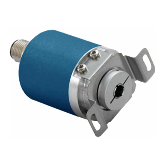
Avtron HS6M Manual de instrucciones - Página 5
Navegue en línea o descargue pdf Manual de instrucciones para Media Converter Avtron HS6M. Avtron HS6M 16 páginas. Hollow shaft 6-15mm

SSI Protocol "S"
The SSI Protocol "S" provides a clocked set of data bits that
represent the encoder position (in turns and within 1 turn). Each bit
is output by the encoder as the clock input transitions.
Preferred cable: Twisted pair with individual and overall shield
grounded at one end only. 24 AWG, copper conductor, capacitance of
52.5 pF/meter (16 pF/foot) terminated in a 100 Ohm resistive load.
Note that resistive losses in long cables may decrease actual voltage
(+Vs) available at the encoder; larger conductors can be used or the
encoder can be powered locally and signal GND brought through the
cable. Maximum transmission speed is limited by cable length as
shown in the figure below.
10K
1.2K
1K
100
10
10K
100K
DATA SIGNALING RATE - bit's
Cable Lenght versus data signaling rate
For more details on SSI, consult Wikipedia:
http://en.wikipedia.org/wiki/Synchronous_Serial_Interface
Set Zero
(input, ACTIVE HIGH, Falling Edge, 10K resistance)
To set the encoder count value to zero, raise Set Zero> 10V, < Vs for
more than 1 second. Upon the Set Zero signal returning to logic zero
(falling edge), the encoder count value will be set to zero.
Set Direction
(input, 10K resistance)
For input logic zero or no connection, the encoder will count UP for
CCW rotation as viewed from the rear end of the encoder.
For input logic 1 (>10V, <Vs), the encoder will count DOWN for CCW
rotation as viewed from the rear of the encoder.
1M
10M
HS6M
Analog Protocol "A"
The analog protocol provides a steady-state analog output which
represents the encoder position over a portion of a turn or any
portion of a turn plus a number of turns. The factory default is 0-16
turns = min/max output. This can be modified by using the Set
Lower and Set Upper End Point inputs similar to most electronic
cam-setting systems (described below.)
Preferred cable: Overall shield grounded at one end only. Twisted
pair cable acceptable but not required. Note that resistive losses
in long cables may decrease actual voltage (+Vs) available at the
encoder; larger conductors can be used or the encoder can be
powered locally and signal GND brought through the cable.
0-
0-
0.5-
Output
5V
10V
4.5V
Signal
"3"
"4"
"7"
Code
Min.
Supply
12V
12V
12V
Voltage
Min.
10k
10k
10k
Load
Max.
Any
Any
Any
Load
Settle
Time
Min.
Travel
0.06 turns /22.5 deg.
Turns
Max.
Travel
65536 turns
Turns
Set Lower End Point 1
(input, ACTIVE HIGH, Falling Edge, 10K resistance)
To set the encoder output to the minimum value at the present
position of rotation, raise Set Lower End Point 1> 10V, < Vs for more
than 1 second. Upon the Set Lower End Point 1 signal returning
to logic zero (falling edge), the encoder output will be set to the
minimum output shown in the output table.
Set Upper End Point 2 (input, ACTIVE HIGH, Falling Edge, 10K
resistance)
To set the encoder output to the maximum value at the present
position of rotation, raise Set Upper End Point 2> 10V, < Vs for more
than 1 second. Upon the Set Upper End Point 2 signal returning
to logic zero (falling edge), the encoder output will be set to the
maximum output shown in the output table.
Reset Upper and Lower End Points to Factory Default (16 turn
scaling)
Restore Factory Endpoint Settings (End Point 1, 2)
(input, ACTIVE HIGH, Falling Edge, 10K resistance)
Raise both Set Lower End Point 1 and Set Upper End Point
2> 10V, < Vs for more than 1 second. Upon both signals returning
to logic zero, the encoder output will be reset to the factory default
scaling of maximum output over 16 turns (only applies to the MT
option, and the present position and the encoder will be set to the
mid-point (8 turns) = 1/2 of the maximum output.
5
0.5-
4-
0-
Units
9.5V
20mA
20mA
"8"
"5"
"6"
12V
15V
15V
Vdc
10k
0
0
ohms
Any
500
500
ohms
80mS
mS
Turns/
Deg.
Turns
