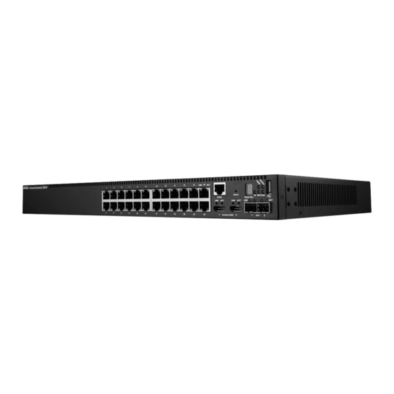
Dell PowerConnect 5548 Manual de introducción - Página 8
Navegue en línea o descargue pdf Manual de introducción para Interruptor Dell PowerConnect 5548. Dell PowerConnect 5548 20 páginas. Powerconnect 5500 series
También para Dell PowerConnect 5548: Notas de publicación (15 páginas)

3 Repeat the process for the rack-mounting bracket on the other side of the
switch.
4 Insert the unit into the 48.26-cm (19-inch) rack, ensuring that the
rack-mounting holes on the switch line up to the mounting holes on the
rack.
5 Secure the unit to the rack with the rack screws (not provided). Fasten the
lower pair of screws before the upper pair of screws. Ensure that the
ventilation holes are not obstructed.
Installing on a Flat Surface
Install the switch on a flat surface if it is not installed on a rack. The surface
must be able to support the weight of the switch and the switch cables.
To install the switch on a flat surface:
1 Attach the self-adhesive rubber pads on each marked location on the
bottom of the chassis.
2 Set the switch on a flat surface, leaving 5.08 cm (2 inches) on each side
and 12.7 cm (5 inches) at the back.
3 Ensure that the switch has proper ventilation.
Connecting the Switch to Power Supplies
Each switch in the stack must be connected to an AC power supply.
The power connectors are positioned on the back panel. Connecting a
Redundant Power Supply (RPS) or Modular Power Supply (MPS) is optional,
but recommended. The RPS or MPS connector is on the back panel of the
switch. The RPS is used for non-PoE switches and MPS is used for PoE
switches.
Figure 1-2. Back-Panel Power Connector
8
Installation
RPS or MPS
A/C Power Supply
