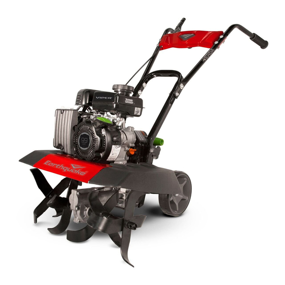
EarthQuake VERSA 20015 SERIES Manual del usuario - Página 6
Navegue en línea o descargue pdf Manual del usuario para Cultivador EarthQuake VERSA 20015 SERIES. EarthQuake VERSA 20015 SERIES 13 páginas. Compact tiller and cultivator

UNPACKING AND ASSEMBLY
CARTON CONTENTS
TILLER ASSEMBLY
•
Hardware Parts Bag:
•
A - (2) M8 x 40 mm Hex Bolt
•
B - (4) M8 x 40 mm Hex Flange Bolt
•
C - (2) M10 x 45 mm Hex Bolt
•
D - (4) M6 x 35mm Hex Flange Bolt
•
F - (6) M8 x 25 mm Flat Washer
•
G - (2) M10 Spring Lock Washer
•
H - (6) M8 Nylock Nut
•
I - (2) M10 Nylock Nut
•
J - (4) M6 Nylock Nut
•
K - (1) Lock Pin
•
L - (2) Tine Shaft Sleeve
•
Manual Parts Bag
•
Left, Right, and Middle Handlebars
•
Left and Right Side Shields
•
Left and Right Tine Sets
•
Pulley Box Cover
•
E - (4) M5 x 25 mm Hex Flange Bolt
•
Drag Stake
•
Bottle of 4-cycle Engine Oil
NOTICE
HANDLE ROTOTILLER WITH CARE. DO NOT DAMAGE
FORWARD CABLE WHEN TRANSPORTING OR OPERATING.
ENGINE IS SHIPPED FROM FACTORY WITHOUT OIL. YOU
MUST ADD ENGINE OIL BEFORE STARTING ENGINE.
WARNING
COMBUSTIBLE DEBRIS CAN CATCH FIRE. IT IS A VIOLATION
OF CALIFORNIA PUBLIC RESOURCE CODE, SECTION 4442,
TO USE OR OPERATE ENGINE-POWERED PRODUCTS
ON ANY FOREST-COVERED, BRUSH-COVERED, OR GRASS-
COVERED LAND UNLESS THE EXHAUST SYSTEM IS
EQUIPPED WITH A SPARK ARRESTER, AS DEFINED IN
SECTION 4442, MAINTAINED IN EFFECTIVE WORKING
ORDER. OTHER STATES OR FEDERAL JURISDICTIONS MAY
HAVE SIMILAR LAWS. CONTACT THE ORIGINAL EQUIPMENT
MANUFACTURER, RETAILER, OR DEALER TO OBTAIN A
SPARK ARRESTER DESIGNED FOR USE WITH THIS PRODUCT.
10
Get parts online at www.GetEarthquake.com or Call 800-345-6007 M-F 8-5 CST
Owner's Manual
VERSA COMPACT TILLER AND CULTIVATOR
4X
Open top of carton and remove packaging materials.
Carefully cut the corners of the carton with a box cutter.
Do not attempt to lift tiller assembly out of box.
FIGURE 2
Carefully remove tiller assembly, additional assembly
components and remaining packaging materials from
package.
FIGURE 3
Remove hand knob bolts from both sides of tiller. Separate
lower handlebar assembly from pulley box and cut zip ties
to remove handlebars.
FIGURE 4 (FOR MODELS 20015/24734)
a
a
c
c
Remove lock pin from one tine set. Slide outer tine and
rotate to align with the second hole position of inner tine,
then secure with lock pin. Repeat for other tine set.
FIGURE 5 (FOR MODELS 20015/24734)
Get parts online at www.GetEarthquake.com or Call 800-345-6007 M-F 8-5 CST
VERSA COMPACT TILLER AND CULTIVATOR
DRAG
STAKE
LOCK
PIN
Remove drag stake from tiller assembly by removing the
lock pin and setting both aside.
FIGURE 4 (FOR MODELS 25780/29241)
b
RIGHT
OUTER
TINE
b
d
LOCK
LEFT
PINS
OUTER
TINE
d
Remove lock pin from one inner tine. Check that arrows
on tines are pointed in the direction of forward rotation
and slide outer tine so that it aligns with the second hole
position of inner tine. Secure with the lock pin. Repeat for
other outer tine.
FIGURE 5 (FOR MODELS 25780/29241)
Owner's Manual
11
